1 Product features
Standard configuration features
1
Page 1: ...Maintenance Service Guide HP t820 Flexible Thin Client ...
Page 2: ...in should be construed as constituting an additional warranty HP shall not be liable for technical or editorial errors or omissions contained herein This document contains proprietary information that is protected by copyright No part of this document may be photocopied reproduced or translated to another language without the prior written consent of Hewlett Packard Company First Edition November ...
Page 3: ...ollow directions could result in bodily harm or loss of life CAUTION Text set off in this manner indicates that failure to follow directions could result in damage to equipment or loss of information NOTE Text set off in this manner provides important supplemental information iii ...
Page 4: ...iv About This Book ...
Page 5: ...eparation 10 Electrostatic discharge information 10 Generating static 11 Preventing electrostatic damage to equipment 11 Personal grounding methods and equipment 12 Grounding the work area 12 Recommended materials and equipment 12 Operating guidelines 13 Routine care 14 General cleaning safety precautions 14 Cleaning the Computer Case 14 Cleaning the keyboard 14 Cleaning the monitor 15 Cleaning th...
Page 6: ... cage fiber NIC assembly holder 34 mSATA drive 35 Hood sensor 36 Installing the fiber NIC assembly 37 WLAN module 41 Graphics board 42 Power switch 43 System board 44 Rear fan 47 Antennas 49 Changing from desktop to tower configuration 52 Port cover 53 Power supply external 54 Appendix A Battery replacement 55 Appendix B Computer Setup F10 Utility BIOS Settings 58 Computer Setup F10 Utilities 58 U...
Page 7: ...9 Basic Troubleshooting 79 Diskless No Flash Unit Troubleshooting 80 Configuring a PXE Server 81 Appendix D Restoring the Flash Image 82 System Requirements 82 Getting Started 82 Formatting a USB Flash Drive 83 Unpacking the Image and Tools for Deployment 83 Deploying with PXE 83 Appendix E Device management 84 Appendix F Adding an Image Restore Tool 85 Appendix G System BIOS 86 Updating or restor...
Page 8: ...Index 94 viii ...
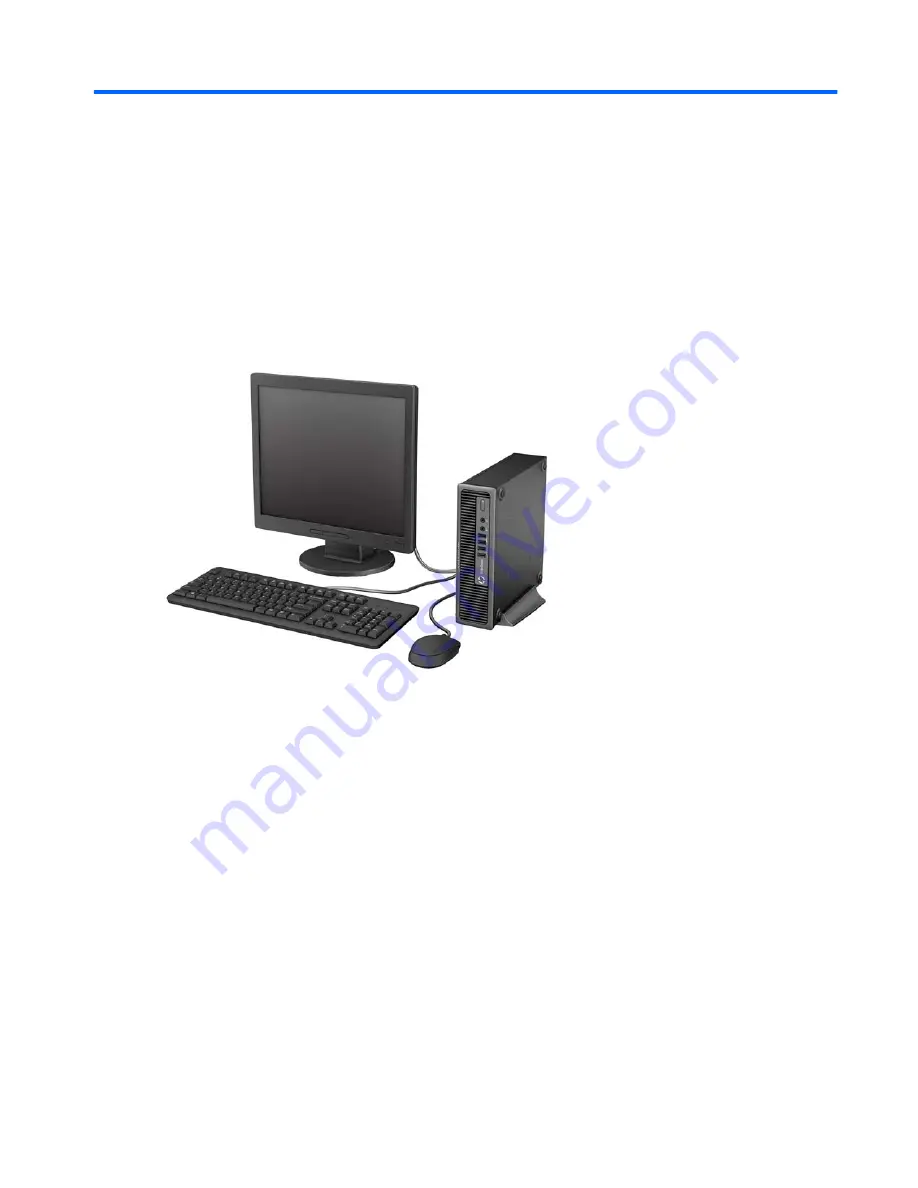
Page 9: ...1 Product features Standard configuration features Standard configuration features 1 ...
Page 10: ...s asking if you want to use the connector for a microphone Line In device or a headphone You can reconfigure the connector at any time by double clicking the Audio Manager icon in the Windows taskbar NOTE The Power On Light is normally white when the power is on If it is flashing red there is a problem with the computer and it is displaying a diagnostic code Refer to theDiagnostics and Troubleshoo...
Page 11: ...s plugged into the blue Line In Audio Connector a dialog box will pop up asking if you want to use the connector for a line in device or a microphone You can reconfigure the connector at any time by double clicking the Audio Manager icon in the Windows taskbar If an MXM graphics card is installed all of the video connectors may be used at the same time However for such a configuration only the dis...
Page 12: ...ach computer has a unique serial number and a product ID number that are located on the exterior of the computer Keep these numbers available for use when contacting customer service for assistance 4 Chapter 1 Product features ...
Page 13: ... 1 Access panel 732763 001 2 Front bezel 732764 001 3 Stand 612496 001 System board includes replacement thermal material For use in models with WES7 737729 001 AC adapter 180W standard 613766 001 135W standard 648964 001 Memory modules PC3 12800 8 GB 689374 001 Computer major components 5 ...
Page 14: ... 3 MB L3 cache 54W 742564 001 Intel Core i5 4570s 2 9 GHz 6 MB L3 cache 65W 732505 001 Drives Description Spare part number mSATA drive 32 GB 719566 001 16 GB 719565 001 Misc boards Description Spare part number AMD Radeon HD 7650A 2GB MXM Graphics 708866 001 HP WLAN 802 11 a b g n 2x2 PCIe NIC 695915 001 6 Chapter 2 Illustrated parts catalog ...
Page 15: ...ludes replacement thermal material not illustrated 689369 001 2 Power switch assembly 732767 001 3 Speaker 689384 001 4 Fan rear 691352 001 5 Front I O panel 732762 001 6 Chassis fan front 732765 001 SATA data cable 25 2 inch 638814 001 Solenoid lock 732772 001 Drive cage 732761 001 Mouse PS2 optical 674315 001 USB optical 674316 001 Keyboard USB 724724 xx1 PS 2 701423 xx1 Misc parts 7 ...
Page 16: ...e 2 GB PC3 12800 689373 001 Memory module 4 GB PC3 12800 689374 001 Memory module 8 GB PC3 12800 689384 001 Speaker 691352 001 Chassis fan rear 695915 001 HP WLAN 802 11 a b g n 2x2 PCIe NIC 701423 xx1 Keyboard PS 2 701424 xx1 Keyboard USB 708866 001 AMD Radeon HD 7650A 2GB MXM Graphics 719565 001 16 GB mSATA drive 719566 001 32 GB mSATA drive 729624 001 Fiber NIC assembly AT 2711FXa PCIe 732505 0...
Page 17: ...t number Description 737729 001 System board for use in models with WES7 includes replacement thermal material 742564 001 Intel Pentium G3220 processor 3 0 GHz 3 MB L3 cache 54W Sequential part number listing 9 ...
Page 18: ...sudden discharge of static electricity from your finger or other conductor can destroy static sensitive devices or microcircuitry Often the spark is neither felt nor heard but damage occurs An electronic device exposed to electrostatic discharge ESD may not appear to be affected at all and can work perfectly throughout a normal cycle The device may function normally for a while but it has been deg...
Page 19: ...a product Preventing electrostatic damage to equipment Many electronic components are sensitive to ESD Circuitry design and structure determine the degree of sensitivity The following packaging and grounding precautions are necessary to prevent damage to electric components and accessories To avoid hand contact transport products in static safe containers such as tubes bags or boxes Protect all el...
Page 20: ...e following precautions Cover the work surface with approved static dissipative material Provide a wrist strap connected to the work surface and properly grounded tools and equipment Use static dissipative mats foot straps or air ionizers to give added protection Handle electrostatic sensitive components parts and assemblies by the case or PCB laminate Handle them only at static free work areas Tu...
Page 21: ... and above the monitor to permit the required airflow Never restrict the airflow into the computer by blocking any vents or air intakes Do not place the keyboard with the keyboard feet down directly against the front of the desktop unit as this also restricts airflow Occasionally clean the air vents on all vented sides of the computer Lint dust and other foreign matter can block the vents and limi...
Page 22: ...the computer case follow the procedures described below To remove light stains or dirt use plain water with a clean lint free cloth or swab For stronger stains use a mild dishwashing liquid diluted with water Rinse well by wiping it with a cloth or swab dampened with clear water For stubborn stains use isopropyl rubbing alcohol No rinsing is needed as the alcohol will evaporate quickly and not lea...
Page 23: ...tor screen with a clean cloth moistened with water or with a towelette designed for cleaning monitors Do not use sprays or aerosols directly on the screen the liquid may seep into the housing and damage a component Never use solvents or flammable liquids on the monitor To clean the monitor body follow the procedures in Cleaning the Computer Case on page 14 Cleaning the mouse Before cleaning the mo...
Page 24: ... cables are routed in such a way that they cannot be caught or snagged by parts being removed or replaced CAUTION When servicing this computer ensure that cables are placed in their proper location during the reassembly process Improper cable placement can damage the computer Lithium coin cell battery The battery that comes with the computer provides power to the real time clock and has a minimum ...
Page 25: ...rom the computer 3 Turn off the computer properly through the operating system then turn off any external devices 4 Disconnect the power cord from the power outlet and disconnect any external devices CAUTION Turn off the computer before disconnecting any cables Regardless of the power on state voltage is always present on the system board as long as the system is plugged into an active AC outlet I...
Page 26: ...ess panel 1 Prepare the computer for disassembly Preparation for disassembly on page 17 2 Loosen the thumbscrew on the rear of the computer 1 slide the access panel toward the rear of the computer then lift it off 2 To install the access panel reverse the removal procedure 18 Chapter 4 Removal and replacement procedures ...
Page 27: ...e computer for disassembly Preparation for disassembly on page 17 2 Remove the access panel Access panel on page 18 3 Lift up the three tabs on the side of the bezel 1 then rotate the bezel off the chassis 2 To install the front bezel reverse the removal procedure Front bezel 19 ...
Page 28: ...epare the computer for disassembly Preparation for disassembly on page 17 2 Remove the access panel Access panel on page 18 3 Remove the front bezel Front bezel on page 19 4 Remove the black screw on the front of the chassis behind the bezel The screw is labeled BEZEL 5 Replace the front bezel 20 Chapter 4 Removal and replacement procedures ...
Page 29: ...6 Install the security screw through the middle front bezel release tab and into the chassis to secure the front bezel in place Front bezel security 21 ...
Page 30: ...ith up to 16 GB of memory DDR3 SDRAM SODIMMs For proper system operation the SODIMMs must be industry standard 204 pin unbuffered non ECC PC3 12800 DDR3 1600 MHz compliant 1 35 volt or 1 5 volt DDR3 SDRAM SODIMMs The DDR3 SDRAM SODIMMs must also support CAS latency 11 DDR3 1600 MHz 11 11 11 timing contain the mandatory Joint Electronic Device Engineering Council JEDEC specification In addition the...
Page 31: ...SODIMM sockets are populated in one channel only The system will operate in a higher performing dual channel mode if the memory capacity of the SODIMM in Channel A is equal to the memory capacity of the SODIMM in Channel B The system will operate in flex mode if the memory capacity of the SODIMM in Channel A is not equal to the memory capacity of the SODIMM in Channel B In flex mode the channel po...
Page 32: ...uter or optional cards Before beginning these procedures ensure that you are discharged of static electricity by briefly touching a grounded metal object For more information refer to Electrostatic discharge information on page 10 When handling a memory module be careful not to touch any of the contacts Doing so may damage the module 1 Prepare the computer for disassembly Preparation for disassemb...
Page 33: ... Prepare the computer for disassembly Preparation for disassembly on page 17 2 Remove the access panel Access panel on page 18 3 Disconnect the fan control cable from the red system board connector labeled CHFAN 1 4 Lift the fan straight up and out of the chassis 2 To install the front fan reverse the removal procedure Front fan 25 ...
Page 34: ... Remove the access panel Access panel on page 18 3 Remove the front bezel Front bezel on page 19 4 Remove the front fan Front fan on page 25 5 Disconnect the speaker cable from the white system board connector labeled SPKR 6 On the outside of the chassis remove the two Torx T8 screws that secure the speaker to the chassis 1 and then from the inside of the chassis slide the speaker up to remove it ...
Page 35: ... disconnect the fan cable from the system board 4 Loosen the four Torx T15 screws that secure the heat sink to the system board and then lift the heat sink from the system board CAUTION Heat sink retaining screws should be removed in diagonally opposite pairs as in an X to even the downward forces on the processor to avoid damage that could require replacing the system board 5 Lay the heat sink on...
Page 36: ...ive covering from the bottom of the heat sink and place it in position atop the processor 4 Secure the heat sink to the system board with the 4 captive screws CAUTION Heat sink retaining screws should be tightened in diagonally opposite pairs as in an X to evenly seat the heat sink on the processor This is especially important as the pins on the socket are very fragile and any damage to them may r...
Page 37: ... and rotate the microprocessor retainer to its fully open position 2 7 Carefully lift the processor from the socket 3 CAUTION Do NOT handle the pins in the processor socket These pins are very fragile and handling them could cause irreparable damage Once pins are damaged it may be necessary to replace the system board To install the processor reverse the removal procedures NOTE After installing a ...
Page 38: ...owing circumstances Power outage Startup failure PC component for example processor or power supply failure Forgotten password NOTE The Smart Cover FailSafe Key is a specialized tool available from HP Be prepared order this key before you need it To obtain a FailSafe Key Contact an authorized HP reseller or service provider Order PN 166527 001 for the wrench style key or PN 166527 002 for the scre...
Page 39: ...ear side of the chassis remove the silver security screw that secures the lock to the chassis 4 From the inside of the chassis lift the lock up to gain access to the system board connector Smart Cover Lock solenoid lock 31 ...
Page 40: ...lowing image for the location of the slots on the back of the chassis in which to install the lock When installing insert the top tabs into the top slots and then rotate the lock downward Then install the security screw on the outside of the computer Plug the connector into the system board connector 32 Chapter 4 Removal and replacement procedures ...
Page 41: ...Smart Cover Lock solenoid lock 33 ...
Page 42: ...e houses is the fiber NIC assembly 1 Prepare the computer for disassembly Preparation for disassembly on page 17 2 Remove the access panel Access panel on page 18 3 Remove the two Torx screws that secure cage to the chassis 1 lift the tab 2 on the cage slide the cage toward the rear of the unit 3 and then pull the cage up and out of the chassis To install the drive cage reverse the removal procedu...
Page 43: ...A drive 1 Prepare the computer for disassembly Preparation for disassembly on page 17 2 Remove the access panel Access panel on page 18 3 Remove the drive cage Drive cage fiber NIC assembly holder on page 34 4 Remove the two Phillips screws 1 that secure the drive to the computer 5 Slide the drive away to remove it from the socket 2 Reverse this procedure to install the mSATA drive mSATA drive 35 ...
Page 44: ...older on page 34 4 Unplug the hood sensor cable from the white system board connector labeled HSENSE 1 and remove the cable from the white clip mounted on the inside chassis wall 2 5 Slide the hood sensor into the chassis to remove it from its slot 3 Disengaging the hood sensor from the chassis may require use of a screwdriver or similar tool To install the hood sensor reverse the removal procedur...
Page 45: ...reparation for disassembly on page 17 2 Remove the access panel Access panel on page 18 3 Remove the drive cage Drive cage fiber NIC assembly holder on page 34 4 Insert the Fiber NIC assembly into the hard drive carrier 5 Insert the four Torx isolation screws to secure the assembly into the carrier Installing the fiber NIC assembly 37 ...
Page 46: ...the two Torx screws that secure the card onto the system board 1 and the insert the FFC cable into the connector on the card 8 Install the hard drive carrier assembly into the hard drive cage For more information see Drive cage fiber NIC assembly holder on page 34 38 Chapter 4 Removal and replacement procedures ...
Page 47: ...rd drive carrier cage and then insert the cable into the connector on the larger fiber card 10 Install the clips in the two locations as shown in the following image and then route the cables through the clips Installing the fiber NIC assembly 39 ...
Page 48: ...on the computer and then inserting the two Torx screws to secure the connector 13 From the inside rear of the computer plug the cables into the connector Plug the white cable into the port labeled R and the green cable into the port labeled T To remove the fiber NIC assembly reverse the removal procedures 40 Chapter 4 Removal and replacement procedures ...
Page 49: ...ge Drive cage fiber NIC assembly holder on page 34 4 Disconnect the two antenna cables from the connectors on the module 1 5 Remove the two Phillips screws 2 that secure the module to the system board 6 Lift the module to a 45 degree angle and then remove the module from the connector by pulling it away at an angle 3 To install the WLAN module reverse the removal procedure Make sure the antenna ca...
Page 50: ...der on page 34 4 Remove the two Torx T8 screws 1 that secure the graphics board to the system board rotate the board upward to a 45 degree angle 2 and the pull it away from the system board connector and out of the computer 3 NOTE Graphics card appearance may vary To install the graphics board reverse the removal procedure If you need to remove the heat sink from the graphics board loosen the four...
Page 51: ...C assembly holder on page 34 5 Disconnect the power switch cable from the system board connector labeled PB LED 6 Remove the power switch cable from atop the front I O bracket 7 From the front of the computer press down or squeeze on the top on the power switch 1 and then rotate it down 2 to disengage it from the chassis 8 Pull the power switch and cable assembly out through the hole in the front ...
Page 52: ...dule on page 41 Graphics board Graphics board on page 42 1 Prepare the computer for disassembly Preparation for disassembly on page 17 2 Remove the access panel Access panel on page 18 3 Remove the front fan Front fan on page 25 4 Remove the drive cage Drive cage fiber NIC assembly holder on page 34 5 Remove the fiber NIC assembly Installing the fiber NIC assembly on page 37 6 Remove the heat sink...
Page 53: ...ve the Torx T15 screw from the right side of the panel that secures it to the front of the chassis b Press the tab on right side of the panel 1 and then swing the right side of the cage away from the chassis to remove it 2 System board 45 ...
Page 54: ...ors are clear of their slots in the chassis 1 13 Lift the rear of the system board until it clears the chassis and then remove the system board from the chassis 2 To install the system board reverse the removal procedure NOTE When replacing the system board you must also change the chassis serial number in the BIOS 46 Chapter 4 Removal and replacement procedures ...
Page 55: ...on page 17 2 Remove the access panel Access panel on page 18 3 Remove the front fan Front fan on page 25 4 Remove the drive cage Drive cage fiber NIC assembly holder on page 34 5 Remove the fiber NIC assembly Installing the fiber NIC assembly on page 37 6 Remove the heat sink Heat sink on page 27 7 Remove the system board System board on page 44 8 From the outside of the chassis remove the four Ph...
Page 56: ...rom the inside of the chassis slide the fan out from underneath the chassis lip and then remove the fan To install the rear fan reverse the removal procedure 48 Chapter 4 Removal and replacement procedures ...
Page 57: ... cage Drive cage fiber NIC assembly holder on page 34 5 Remove the fiber NIC assembly Installing the fiber NIC assembly on page 37 6 Remove the heat sink Heat sink on page 27 7 Remove the system board System board on page 44 8 Remove the rear fan Rear fan on page 47 9 To remove the front antenna from the inside of the front of the chassis remove the antenna from the clips built into the base pan 1...
Page 58: ...s 2 and then pull the antenna out of the hole it routes through 3 12 To remove the rear antenna from the inside of the front of the chassis remove the antenna from the plastic clips attached to the side of the chassis 50 Chapter 4 Removal and replacement procedures ...
Page 59: ...de of the rear of the chassis remove the two Torx T8 screws that secure the antenna to the chassis 14 Pull the antenna through the hole it routes through To install the rear fan reverse the removal procedure Antennas 51 ...
Page 60: ...board as long as the system is plugged into an active AC outlet You must disconnect the power cord to avoid damage to the internal components of the computer 5 Orient the computer so that its left side is facing down and place the computer firmly down into the stand 6 Reconnect the external equipment plug the power cord into a power outlet and turn the computer on NOTE Ensure at least 10 2 centime...
Page 61: ... slots on the rear of the chassis then slide the cover to the right to secure it in place 2 NOTE For security purposes you can install an optional cable lock to the chassis that locks the port cover and secures the computer The port cover is secured in place by a retention lever just inside the port cover opening To remove the port cover pull the lever back towards the port cover opening 1 then sl...
Page 62: ...WARNING To reduce potential safety issues only the power supply provided with the computer a replacement power supply provided by HP or a power supply purchased as an accessory from HP should be used with the computer 54 Chapter 4 Removal and replacement procedures ...
Page 63: ...optional equipment Before beginning these procedures ensure that you are discharged of static electricity by briefly touching a grounded metal object NOTE The lifetime of the lithium battery can be extended by plugging the computer into a live AC wall socket The lithium battery is only used when the computer is NOT connected to AC power HP encourages customers to recycle used electronic hardware H...
Page 64: ...on positive side up The battery holder automatically secures the battery in the proper position Type 2 a To release the battery from its holder squeeze the metal clamp that extends above one edge of the battery When the battery pops up lift it out 1 b To insert the new battery slide one edge of the replacement battery under the holder s lip with the positive side up Push the other edge down until ...
Page 65: ...the following steps to complete this procedure 8 Replace the access panel 9 Plug in the computer and turn on power to the computer 10 Reset the date and time your passwords and any special system setups using Computer Setup 11 Lock any security devices that were disengaged when the access panel was removed 57 ...
Page 66: ...To manually switch to Post Messages Enabled during POST press any key except F1 through F12 Establish an Ownership Tag the text of which is displayed each time the system is turned on or restarted Enter the Asset Tag or property identification number assigned by the company to this computer Enable the power on password prompt during system restarts warm boots as well as during power on Establish a...
Page 67: ...ter Setup Utilities menu File Storage Security Power and Advanced 5 Use the arrow left and right keys to select the appropriate heading Use the arrow up and down keys to select the option you want then press Enter To return to the Computer Setup Utilities menu press Esc 6 To apply and save changes select File Save Changes and Exit If you have made changes that you do not want applied select Ignore...
Page 68: ...age file located on removable media Replicated Setup Save to Removable Media Saves system configuration to a formatted USB flash media device Restore from Removable Media Restores system configuration from a USB flash media device Default Setup Save Current Settings as Default Saves the current system configuration settings as the default to be used whenever Apply Defaults and Exit is selected Res...
Page 69: ...SB optical drive are checked for a bootable operating system image Each device on the list may be individually excluded from or included for consideration as a bootable operating system source EFI boot sources always have precedence over legacy boot sources Specify the order in which legacy boot sources such as a network interface card internal drive or USB optical drive are checked for a bootable...
Page 70: ...password is set Allows you to enable disable Lock Legacy Resources determines whether or not Windows Device Manager is allowed to change resource settings for serial and parallel ports Setup Browse Mode appears if a setup password is set allows viewing but not changing the F10 Setup Options without entering setup password Default is enabled Password prompt on F9 F12 requires setup password to use ...
Page 71: ...e UUID can only be updated if the current chassis serial number is invalid These ID numbers are normally set in the factory and are used to uniquely identify the system Keyboard locale setting for System ID entry Master Boot Record Security Restores the backup Master Boot Record to the current bootable disk Default is disabled Only appears if all of the following conditions are true MBR security i...
Page 72: ...S management of Embedded Security Device some models enable disable This option allows the user to limit operating system control of the Embedded Security Device Changing this setting requires turning the computer off and then back on This option allows the user to limit OS control of the Embedded Security Device Default is disabled Reset of Embedded Security Device through OS some models enable d...
Page 73: ...Hardware Power Management SATA Power Management Enables or disables SATA bus and or device power management Default is enabled S5 Maximum Power Savings Turns off power to all nonessential hardware when system is off to meet EUP Lot 6 requirement of less than 0 5 Watt power usage Default is disabled PCI Express x16 Slot 1 Sets Active State Power Management ASPM of the bus ASPM lets you set lower po...
Page 74: ... soon as power is restored Previous state causes the computer to power on automatically as soon as power is restored if it was on when power was lost NOTE If you turn off power to the computer using the switch on a power strip you will not be able to use the suspend sleep feature or the Remote Management features POST Delay in seconds Enabling this feature will add a user specified delay to the PO...
Page 75: ...dels does not affect external speakers Default is enabled NIC Option ROM Download PXE disabled The BIOS contains an embedded NIC option ROM to allow the unit to boot through the network to a PXE server This is typically used to download a corporate image to a hard drive The NIC option ROM takes up memory space below 1MB commonly referred to as DOS Compatibility Hole DCH space This space is limited...
Page 76: ...s Disable Enable Network Server Mode Disable Enable Setup Browse Mode Disable Enable Password prompt on F9 F12 Enable Disable Cover Removal Sensor Disable Notify User Setup Password Front USB Ports Enable Disable Front USB Port 1 2 Disable Enable Rear USB Ports Enable Disable Rear USB Port 1 2 Disable Enable Rear USB3 Port 1 2 Disable Enable Accessory USB Ports Enable Disable Accessory USB Port 1 ...
Page 77: ...vings Extended Normal Auto Unique Sleep State Blink Rates Disable Enable S5 Maximum Power Savings Disable Enable SATA Power Management Disable Enable Fan Idle Mode POST Mode QuickBoot FullBoot FullBoot Every 07 Days 14 Days 21 Days 28 Days Clear Memory POST Messages Disable Enable Press ESC for Startup Menu Prompt Enable Disable Option ROM Prompt Enable Disable Remote Wakeup Boot Source Local Hard...
Page 78: ...ble Default Setup Leave Defaults As Is No Update Save Current Settings as Default Restore Factory Settings as Default Apply Defaults and Exit Do Not Apply Apply Power On Password na na Setup Password na na NOTE Settings that can be controlled from the operating system with repset can also be controlled remotely by sending the client an Altiris job that uses the repset tool to apply the setting cha...
Page 79: ...tection and initialization NOTE If one of the tests fails the unit will simply stop but the LED will stay on If the video test fails the unit beeps There are no messages sent to video for any of these failed tests NOTE After the video is initialized anything that fails will have an error message NOTE RJ 45 LEDs are located inside the RJ 45 connector on the top rear panel of the thin client The LED...
Page 80: ... Computer Setup 4 Navigate to Power Hardware Power Management 5 Set S5 Maximum Power Savings as follows Disable WOL Enabled Enable WOL Disabled 6 Press F10 to accept any changes 7 Select File Save Changes and Exit Power On Sequence At power on the flash boot block code initializes the hardware to a known state then performs basic power on diagnostic tests to determine the integrity of the hardware...
Page 81: ...hardware to determine its functionality and configuration If a diagnostic test fails during hardware initialization the unit simply stops There are no messages sent to video NOTE You may try to restart the unit and run through the diagnostic tests a second time to confirm the first shutdown The following table lists the tests that are performed on the unit Table C 2 Power On Diagnostic Test Test D...
Page 82: ...able C 3 Diagnostic Front Panel LEDs and Audible Codes Activity Beeps Possible Cause Recommended Action White Power LED On None Computer on None White Power LED flashes every two seconds None Computer in Suspend to RAM mode some models only or normal Suspend mode None required Press any key or move the mouse to wake the computer Red Power LED flashes two times once every second followed by a two s...
Page 83: ...y 3 Replace the system board Red Power LED flashes five times once every second followed by a two second pause Beeps stop after fifth iteration but LEDs continue until problem is solved 5 Pre video memory error CAUTION To avoid damage to the memory modules or the system board you must unplug the computer power cord before attempting to reseat install or remove a memory module 1 Reseat memory modul...
Page 84: ...the system board System does not power on and LEDs are not flashing None System unable to power on Press and hold the power button for less than 4 seconds If the hard drive LED turns white the power button is working correctly Try the following 1 Remove the power cord from the computer 2 Open the computer and press the yellow CMOS button on the system board for 4 seconds located near the front USB...
Page 85: ... for an expansion card s option ROM Internal PXE option ROM is used for booting from the NIC to a PXE server 161 Real Time Clock Power Loss Invalid time or date in configuration memory RTC real time clock battery may need to be replaced Reset the date and time under Control Panel Computer Setup can also be used If the problem persists replace the RTC battery See the Removal and Replacement section...
Page 86: ... fan cable 3 Replace front chassis fan 912 Computer Cover Has Been Removed Since Last System Startup Computer cover was removed since last system startup No action required 921 Device in PCI Express slot failed to initialize There is an incompatibility problem with this device and the system or PCI Express Link could not be retrained to an x1 Try rebooting the system If the error reoccurs the devi...
Page 87: ...lugged into the thin client unit Power connector Keyboard Mouse Network RJ 45 connector Monitor The thin client unit does not power on 1 Verify that the power supply is good by installing it on a known working unit and testing it If the power supply does not work on the test unit replace the power supply 2 If the unit does not work properly with the replaced power supply have the unit serviced The...
Page 88: ...d disconnected to a running platform as long as you do not reboot the system If problems occur disconnect the unknown USB peripheral and reboot the platform Video does not display 1 Verify that the monitor brightness is set to a readable level 2 Verify the monitor is good by connecting it to a known working computer and ensure its front LED turns green assuming the monitor is Energy Star compliant...
Page 89: ... the DHCP IP information appears on the screen If the unit does not boot to the network the server is not configured to PXE If you missed the F12 cue the system will try to boot to the ATA flash that is not present The message on the screen will read ERROR Non system disk or disk error Replace and press any key when ready Pressing any key will restart the boot cycle Configuring a PXE Server NOTE A...
Page 90: ...oad the appropriate image from http www hp com Getting Started There are two deployment options supported by this utility You can choose to do one or more of the following using your personal computer Create a bootable flash image on a USB flash device Unbundle the image to a directory for use in a custom deployment scenario or PXE image Download and run the Package for the Web deliverable an exe ...
Page 91: ... drive to another drive 4 Click Format Connect the bootable USB flash device to the thin client Only one bootable USB device may be attached to the thin client during this process NOTE Do not use USB 3 0 devices 5 Restart the thin client 6 When prompted Do you want to continue Y N click Y to begin the image restore process on the thin client Unpacking the Image and Tools for Deployment Click Deplo...
Page 92: ... used to manage the full life cycle of HP thin clients to include Discover Asset Management Deployment and Configuration For more information on HP Device Manager please visit www hp com go hpdm If you wish to manage the t820 with other management tools such as Microsoft SCCM or LANDesk go to www hp com go clientmanagement for more information 84 Appendix E Device management ...
Page 93: ... that you will use to deploy the original thin client image 5 Click the name of the new job 6 Near the upper right side of the screen click Add 7 Select Run Script from the menu 8 Type full path images ibr exe y images flash xx hd0 9 Under In which OS would you like to run this script Click DOS 10 Click Finish 11 You can now drag and drop the job onto the appropriate machine s or schedule it to ru...
Page 94: ...ay the available options for this utility type Path HPQFlash at a command prompt or local search box If the system has a BIOS Setup password enabled then HPQFlash will prompt for you to enter the password before completing the flash process You can also run HPQFlash exe from a USB storage device including flash memory devices and external hard drives as follows 1 Insert the device and take note of...
Page 95: ... Flash folder to the USB device boot the computer from the USB device and execute the DOSFlash application To see a more complete description of the DOS flash utilities view DOSFlash txt located in the DOS Flash folder of the SoftPaq This folder also contains the required binary image of the BIOS The binary image file is named xxx_MMmm bin where xxx is the BIOS family MM is the major version numbe...
Page 96: ... the BIOS re enable the functions and restart the system so that you can take new measurements BootBlock Emergency Recovery Mode In the event of a failed BIOS update for example if power is lost while updating the System BIOS may become corrupted BootBlock Emergency Recovery Mode detects this condition and automatically searches the root directory of the hard drive and any USB media sources for a ...
Page 97: ...dited agency responsible for evaluation in the country where the power cord set will be installed 2 The power cord set must have a minimum current capacity of 10A 7A Japan only and a nominal voltage rating of 125 or 250 volts AC as required by each country s power system 3 The diameter of the wire must be a minimum of 0 75 mm2 or 18AWG and the length of the cord must be between 1 8 m 6 feet and 3 ...
Page 98: ... fittings appliance coupler and wall plug must bear the certification mark of the agency responsible for evaluation in the country where it will be used 2 The flexible cord must be Type SVT or equivalent No 18 AWG 3 conductor The wall plug must be a two pole grounding type with a NEMA 5 15P 15A 125V or NEMA 6 15P 15A 250V configuration 3 Appliance coupler flexible cord and wall plug must bear a T ...
Page 99: ...aken to restore the Non Volatile memory found in the Intel based HP t820 Flexible Thin Client systems 1 Download the latest BIOS system ROM from the HP website 2 Follow the instructions for flashing the BIOS 3 Shut down the computer 4 Power on the computer and enter the Computer Setup Utility as follows a Press the Esc key when the Press the ESC key for Startup Menu prompt appears near the bottom ...
Page 100: ...labeled PSWD and remove it 21 Remove the AC power wait 10 seconds until the unit AC power drains out then press the clear CMOS button on the system board This is typically a yellow push button labeled CMOS 22 Replace the hood and AC power cord and turn the computer on The passwords are now cleared and all other user configurable non volatile memory settings are reset to their factory default value...
Page 101: ...change is 10 C 50 F Hr The upper limit may be limited by the type and number of options installed Relative Humidity noncondensing Operating 28 C 82 4 F max wet bulb Nonoperating 38 7 C 101 66 F max wet bulb 10 90 5 95 10 90 5 95 Maximum Altitude unpressurized Operating Nonoperating 10 000 ft 30 000 ft 3 048 m 9 144 m Power Supply Operating Voltage Range Rated Voltage Range1 Rated Line Frequency Op...
Page 102: ... troubleshooting 80 drive cage kit spare part number 7 34 drive rail removal and replacement 34 E electrostatic discharge ESD 10 preventing damage 11 error codes 74 messages 77 F fan spare part number 7 8 fiber NIC assembly installing 37 spare part number 8 37 flashing LEDs 74 formatting a flash drive 83 front bezel removal and replacement 19 security 20 spare part number 5 8 19 front fan removal ...
Page 103: ...stem board 44 WLAN tuner module 41 removing battery 55 resetting the Administrator password 73 restore 85 restoring the flash image 82 S safety precautions cleaning 14 screws correct size 16 security front bezel 20 serial number locations 4 service considerations 15 Smart Cover Lock spare part number 30 software servicing computer 15 solenoid lock removal and replacement 30 spare part number 30 so...