HP StorageWorks MSL5000 series User Manual Download Page 48

3–10

MSL5000 Series Library User Guide

Library Configuration

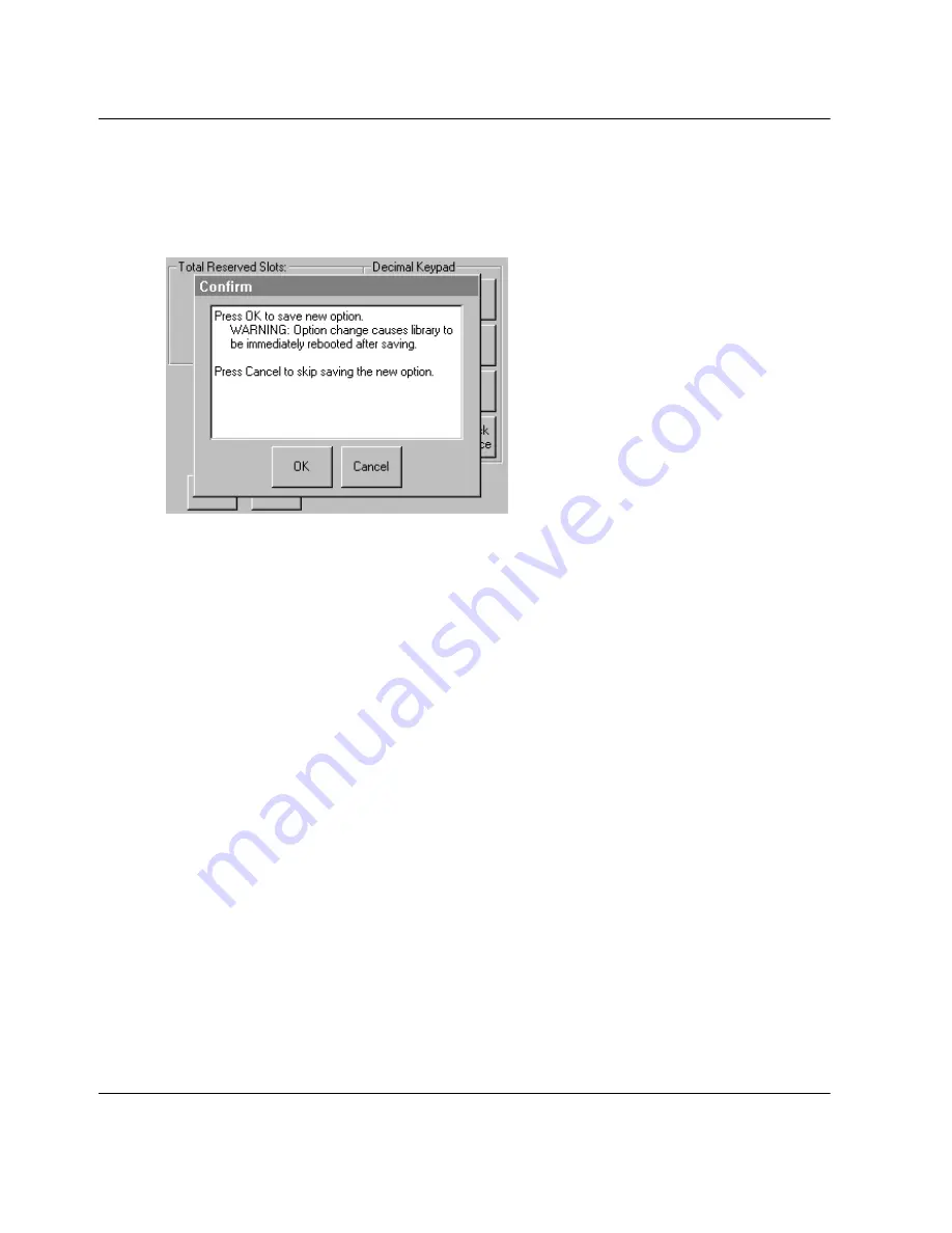
4. Enter the number of slots to reserve and then press Save to confirm your change. 

A confirmation screen appears on the display (see Figure 3–11). Press 

OK

 to 

save.

Figure 3–11:  Total reserved slots confirmation screen

5. Press the 

Back

 button repeatedly to return to the Main menu screen. Your choice 

takes effect the next time you boot the library.

Summary of Contents for StorageWorks MSL5000 series

Page 1: ...s MSL5000 series library user guide Part Number 231910 003 Third Edition August 2002 This guide is to be used as step by step instructions for installing and as a reference for operating troubleshooting and upgrading ...

Page 2: ...ary information which is protected by copyright No part of this document may be photocopied reproduced or translated into another language without the prior written consent of Hewlett Packard The information contained in this document is subject to change without notice HP Compaq and StorageWorks are trademarks of Hewlett Packard Company in the U S and or other countries Compaq Computer Corporatio...

Page 3: ...ssories 1 2 Tape Drives 1 3 Magazines 1 4 Power Supplies 1 5 Robotics 1 7 Library Controller Board 1 8 Factory Defined Accessory PCI Slots 1 9 Embedded Fibre Channel Board 1 10 Front Panel Indicators 1 10 Multi Unit Library Systems 1 11 2 Installation Setting up the Tabletop Model 2 2 Converting a Tabletop Model to a Rackmount Model 2 3 Setting up the Rackmount Model 2 4 Applying Power to the Libr...

Page 4: ... GUI Touch Screen 4 5 Host System 4 6 Inserting and Removing Tape Cartridges 4 6 Removing Magazines 4 7 Inserting Cartridges into a Magazine 4 8 Using Mail Slots Left Magazines Only 4 10 Barcode Labels 4 11 Library Display Screens and Options 4 13 Initialization Screen 4 13 Library Status Screen 4 14 Technical Support Information Option 4 15 Mail Slot Access Option Left Magazines Only 4 15 Magazin...

Page 5: ... 6 Library Configuration 5 7 SCSI Configuration 5 8 Drive Configuration 5 9 Functions 5 10 History 5 11 6 Maintenance Running a Cleaning Cartridge 6 2 Automatically Running a Cleaning Cartridge 6 2 Manually Running a Cleaning Cartridge 6 2 Running a Cleaning Cartridge From a Mail Slot 6 3 Running a Cleaning Cartridge From a Tape Cartridge Slot 6 3 Running a Cleaning Cartridge From a Cleaning Slot ...

Page 6: ...y Compliance Notices Federal Communications Commission Notice A 1 Class A Equipment A 1 Class B Equipment A 2 Modifications A 2 Cables A 2 Declaration of Conformity for products marked with the FCC logo United States only A 2 Canadian Notice Avis Canadien A 3 Class A Equipment A 3 Class B Equipment A 3 European Union Notice A 4 Taiwanese Notice A 4 Japanese Notice A 5 B Specifications Operational ...

Page 7: ...ples E 2 Pass Through Mechanism Cabling E 13 Configuration Examples E 13 F Optional Fibre Channel Card Host Prerequisites F 1 Connectors and Indicators F 2 Power Indicator F 2 Serial Port F 2 Ethernet Port F 3 Fibre Channel Port F 3 SCSI VHDCI Connectors F 3 Configuration F 4 Default Ethernet Settings F 4 Configuration Examples F 5 Resetting the Fibre Channel Card F 8 Index ...

Page 8: ......

Page 9: ...s Bold Home Print Screen Num Lock Esc PgUp A plus sign between two keys means that you should press them simultaneously Ctrl A Ctrl Home Alt Ctrl Del Menu Items Directory Names Button Names Dialog Box Names Initial Caps for UNIX AIX and Solaris directory names the exact case of every character is displayed On the File menu choose Save Save the file in the C StorageSets Default directory UNIX AIX S...

Page 10: ...se SET THIS_CONTROLLER to change parameters To manage storage enter RUN sysmgr exe UNIX AIX Solaris To list files give the ls command Drive Names Navigate to your CD ROM drive usually D or E filenames Unless case sensitive use lowercase italics If filenames are case sensitive UNIX AIX Solaris or are easier to understand with some upper case letters the exact case of each character is displayed To ...

Page 11: ...er presents clarifying information or specific instructions NOTE Text set off in this manner presents commentary sidelights or interesting points of information Symbols on Equipment Any enclosed surface or area of the equipment marked with these symbols indicates the presence of electrical shock hazards Enclosed area contains no operator serviceable parts WARNING To reduce the risk of injury from ...

Page 12: ...roduct or assembly marked with these symbols indicates that the component exceeds the recommended weight for one individual to handle safely WARNING To reduce the risk of personal injury or damage to the equipment observe local occupational health and safety requirements and guidelines for manually handling material Rack Stability WARNING To reduce the risk of personal injury or damage to the equi...

Page 13: ...ed on the HP website http thenew hp com country us eng support html Be sure to have the following information available before you call Technical support registration number if applicable Product serial numbers Product model names and numbers Applicable error messages Operating system type and revision level Detailed specific questions Product Website The HP website has the latest information on t...

Page 14: ......

Page 15: ...library SCSI interface to host system supports Low Voltage Differential LVD The tape drives and robotics control functions each use separate SCSI connections and SCSI ID addresses Library SCSI I O is provided through two VHDCI series 68 pin Micro D SCSI connectors located at the rear of the unit directly under each tape drive Robotics SCSI I O is provided through two VHDCI series 68 pin Micro D SC...

Page 16: ...e tape cartridge magazines and robotics capable of random or sequential tape cartridge operation MSL5052 MSL5060 libraries contain up to four tape drives four removable tape cartridge magazines and robotics capable of random tape cartridge operation Accessories Contact your authorized service provider or visit the HP website at www compaq com storage tape_index html for the most current list of ac...

Page 17: ...up to four tape drives see Figure 1 1 SCSI I O is accomplished through two VHDCI series 68 pin Micro D SCSI connectors located at the rear of the library directly beneath each tape drive Figure 1 1 Library tape drive locations 1 Tape Drive 0 2 Tape Drive 1 3 Tape Drive 2 4 Tape Drive 3 2 1 2 1 4 3 ...

Page 18: ... of the library each left tape magazine includes a mail slot which is accessible when that magazine door is open Pivoting forward this mail slot feature lets you insert or remove a single tape without having to unlock remove and reinventory the magazine If a full tape cartridge magazine is required the library can be reconfigured to recognize each mail slot as a standard data slot The right tape m...

Page 19: ...raphical User Interface GUI touch screen however a manual power disconnect switch located at the rear of each power supply is provided CAUTION The power supply is not to be removed by the operator Hazardous voltage is present in the cavity if the power cord is not removed Power supplies can be easily replaced in maintenance service mode using a 1 Phillips screwdriver to remove the power supply bra...

Page 20: ...he MSL5052 MSL5060 the left AC power receptacle is for the bottom power supply The right AC power receptacle is for the top power supply 1 Power On LED lights after touching the front panel display 2 Power Supply Release Latch 3 Power Switch 4 Power Supply 5 AC Power Cord s 6 Power supply bracket ...

Page 21: ...sts of the tape drives tape cartridge magazines and an optional Pass Through Mechanism PTM The cartridge shuttle assembly includes a mounted barcode reader for scanning tape cartridges installed in the magazines and tape drives IMPORTANT Both full barcode reader scan and physical scan are conducted each time the library is initially powered up or each time a tape magazine is accessed using normal ...

Page 22: ...n when configured as standalone or master The library controller board is installed in a card cage at the rear of the library and can be serviced with using only a 1 Phillips screwdriver see Figure 1 5 IMPORTANT For MSL5000 series libraries the library controller board must be installed in the right slot of the card cage area upper card cage area for the MSL5052 MSL5060 The remaining slots on the ...

Page 23: ...amage your MSL5000 series library and will void product warranty Follow all installation configuration and operating instructions shipped with the option card upgrade kit IMPORTANT For MSL5000 series libraries only the library controller board must be installed in the right slot of the card cage area upper card cage area for the MSL5052 MSL5060 Figure 1 6 Library card cages 1 Library Controller Bo...

Page 24: ...ed to either a Fibre Channel Arbitrated Loop FC AL or switched fabric See Appendix F for additional information on configuring and using the optional Fibre Channel board Front Panel Indicators The library front panel indicators consist of the following Viewing window lets you visually check the internal operations of the library GUI touch screen manually operated to set up and configure the librar...

Page 25: ...ight libraries not exceeding 40 Units 40U in total stacked height can also be used A multi unit library configuration appears to the host computer system and application software as a single library For multi unit applications the top library becomes the master unit and all other libraries are slave units WARNING The PTM continues to function each time a slave library is physically removed from th...

Page 26: ...1 12 MSL5000 Series Library User Guide Introduction Figure 1 8 Library PTM mounting location 1 PTM Interface Connector 2 PTM Mounting Cover removal required for PTM installation 2 1 2 1 ...

Page 27: ...SL5000 series library Sections in this chapter include Setting up the tabletop model Converting a tabletop model to a rackmount model Setting up the rackmount model Applying power to the library SCSI cable configurations IMPORTANT Be sure to keep and store all shipping materials from your MSL5000 series library ...

Page 28: ...ing grills at the front and the fans at the rear of the library are not obstructed Allow 18 inches 50 cm of clearance at the front and rear for magazine and hot plug tape drive access without the need to reposition the library NOTE To reduce tabletop clearance requirements temporarily move the library forward or rearward to access the hot plug drive shoes and magazines respectively Figure 2 1 Tabl...

Page 29: ...l To make a tabletop library ready for rack enclosure installation 1 Remove the rubber feet Remove the cover Attach the inner rails to the library using the supplied allen wrench and screws Tighten the screws until snug Proceed to Setting up the Rackmount Model Figure 2 2 Converting a tabletop model ...

Page 30: ... Library template 9000 rack enclosure shown NOTE For HP rack system e and AlphaServer H9A rack enclosures refer to the appropriate rack rail adapter kit 2 Remove the template and then attach the rails using the supplied fasteners see Figure 2 3 The front rail brackets are threaded to directly accept screws The rear brackets are not threaded and require cage clip nuts in the rack enclosure rear ver...

Page 31: ... Guide 2 5 Installation a Fully extend the slide rails 1 on both sides of the rack enclosure until they lock b Slide the inner guide rail 2 as far as possible to the front of the rail assembly Figure 2 4 Installing the rails 1 2 ...

Page 32: ...cause the rack enclosure to overbalance 4 Using two people lift the library and visually align the inner and intermediate slide rails CAUTION The library is heavier toward the tape drive end rear 5 Carefully insert the library s inner slide rails 3 into the extended intermediate slide rails 2 see Figure 2 4 6 Slide the library into the rack enclosure until the rail locks are engaged WARNING A rack...

Page 33: ...ed to block the latch mechanism IMPORTANT Do not close the doors You must have access to the two retaining screws to complete the installation If necessary see chapter 4 Operation for information on how to manually open the library doors 11 With the doors open secure the front panel to the rack enclosure using the two retaining screws see Figure 2 5 Close the doors You can now cable the library ...

Page 34: ...2 8 MSL5000 Series Library User Guide Installation Figure 2 6 Securing the library 1 Left Retaining Screw 2 Right Retaining Screw 2 1 2 1 ...

Page 35: ...ower supply MSL5052 MSL5060 only 2 Toggle each power switch 2 on 3 Press anywhere on the Graphical User Interface GUI touch screen 3 to activate the display and turn the library on IMPORTANT The SCSI terminator must always be connected to the library controller board for proper operation if configured as a master or standalone NOTE Using a piece of tape to lift one corner carefully remove the appl...

Page 36: ...ies library See Appendix E for additional configuration examples Supported SCSI Cables NOTE For optimum performance a maximum of two tape drives per SCSI bus is recommended Each of the tape drives in the library and the library controller constitute an independent SCSI target When any two or more devices are connected to the same SCSI bus each separate SCSI device must be assigned a unique SCSI ID...

Page 37: ...s a typical SCSI cable configuration for a library with two tape drives installed using a dual host system Figure 2 8 MSL5026 MSL5030 SCSI cable configuration two tape drives dual host system 1 SCSI Terminator 2 To Library Controller Board 3 To Host System 4 SCSI Terminator 5 To Host System 2 1 5 3 4 ...

Page 38: ...s dual host system IMPORTANT The short 9 8 inch 0 25M jumper cables 5 are designed for this use only Stretching either one to reach the library controller board can damage the cable Use the longer 19 8 inch 0 5M cable 2 to connect the tape drive and the library controller board See Appendix E for additional configuration examples 1 SCSI Terminator 2 0 5M jumper cables 3 RS 232 diagnostic cable for...

Page 39: ...figuration This chapter explains how to configure an HP StorageWorks MSL5000 series library for normal operation Sections in this chapter include Factory default configuration settings Setting a SCSI ID Setting up a reserved slot Setting up your network ...

Page 40: ...slot Setting up a network Change configuration settings using the Graphical User Interface GUI touch screen For a complete description of how the GUI touch screen works see Chapter 4 Operation Setting a SCSI ID Each tape drive installed in the library requires a unique SCSI ID The information provided in this section shows you how to set a SCSI ID To set a SCSI ID 1 Turn the library on and wait un...

Page 41: ...tial SCSI options screen by selecting the To return to the previous SCSI options screen select the or Back button to return to the Menu screen 5 For example to set the Drive 0 Bus ID to 3 a Select the box next to the text Drive 0 Bus ID The Drive 0 Bus ID screen appears on the display see Figure 3 2 This screen displays the current Drive 0 Bus ID along with the new value that you request Figure 3 ...

Page 42: ... your request A confirmation screen appears on the display see Figure 3 3 Figure 3 3 SCSI ID confirmation screen d Touch OK to confirm A new SCSI ID now appears in the Drive 0 Bus ID data field see Figure 3 4 Figure 3 4 Drive 0 bus ID data field screen MSL5026 shown 6 Repeat this procedure to set any remaining SCSI IDs 7 Touch the Back button repeatedly to return to the Main menu screen ...

Page 43: ...g Standard tape cartridge slots are numbered from the front of the magazine to the rear see Figure 3 5 and Figure 3 7 If you reserve one slot it becomes Reserved Slot 1 in the last slot of the last magazine Additional reserved slots continue in this rear to front pattern Figure 3 5 Reserved slot locations DLT SDLT MSL5026 1 Reserved Slot 1 2 Reserved Slot 2 3 Reserved Slot 3 4 Mail Slot Left Magaz...

Page 44: ...e Library Configuration Figure 3 6 Reserved slot locations LTO MSL5030 1 Reserved Slot 1 2 Reserved Slot 2 3 Reserved Slot 3 Mail Slot Left Magazine Only 4 2 3 1 0 1 2 3 4 5 6 7 8 9 10 11 12 13 14 15 16 17 18 19 20 21 22 23 24 25 26 27 28 ...

Page 45: ...ibrary Configuration Figure 3 7 Reserved slot locations DLT SDLT MSL5052 1 Reserved Slot 1 2 Reserved Slot 2 3 Reserved Slot 3 4 Mail Slot Left Magazine Only 36 25 26 27 28 29 30 31 32 33 34 35 49 38 39 40 41 42 43 44 45 46 47 48 37 4 1 2 3 ...

Page 46: ...rary Configuration Figure 3 8 Reserved slot locations LTO MSL5060 1 Reserved Slot 1 2 Reserved Slot 2 3 Reserved Slot 3 Mail Slot Left Magazine Only 4 2 3 1 29 30 31 32 33 34 35 36 37 38 39 40 41 42 43 44 45 46 47 48 49 50 51 52 53 54 55 56 57 ...

Page 47: ...ns area 2 From the Library options screen press the to scroll to the screen that contains the Total Reserved Slots option see Figure 3 9 Figure 3 9 Total reserved slots screen 3 Press the associated box next to the Total Reserved Slots option A numeric keypad appears on the display see Figure 3 10 Figure 3 10 Reserved slots numeric keypad screen ...

Page 48: ...and then press Save to confirm your change A confirmation screen appears on the display see Figure 3 11 Press OK to save Figure 3 11 Total reserved slots confirmation screen 5 Press the Back button repeatedly to return to the Main menu screen Your choice takes effect the next time you boot the library ...

Page 49: ...d addresses through the front panel To set a fixed address 1 From the Menu screen touch Network from the Edit Options area The IP Address Determination screen appears see Figure 3 12 Figure 3 12 IP address determination screen 2 Touch the IP Address Determination option see Figure 3 12 and then the User Specified IP Address option see Figure 3 13 Figure 3 13 User specified IP address screen 3 Touc...

Page 50: ...Configuration 4 Touch each IP address option and then use the keypad to enter each IP address see Figure 3 14 5 Save and confirm your selections Figure 3 14 Fixed IP address screen 6 Press the Back button repeatedly to return to the Main menu screen ...

Page 51: ...de 4 1 4 Operation This chapter describes how to operate an HP StorageWorks MSL5000 series library Sections in this chapter include the following Front panel Inserting and removing tape cartridges Library display screens and options ...

Page 52: ...ncludes the left and right magazine doors a Graphical User Interface GUI touch screen a library status LED and a viewing window see Figure 4 1 Figure 4 1 Library front panel 1 Left Magazine Door 2 Viewing Window 3 GUI Touch Screen 4 Library Status LED 5 Right Magazine Door 1 2 3 4 5 1 2 3 4 5 ...

Page 53: ...ng a small metal pin or paper clip into the mechanical releases see Figure 4 2 CAUTION The magazine doors must only be opened manually in an emergency Failure to follow normal procedures can cause data loss and equipment damage NOTE The library may not perform a complete inventory each time a magazine is manually removed and then replaced using the emergency release Figure 4 2 Magazine door mechan...

Page 54: ...uch Screen 2 Library Status LED Table 4 1 Library Status LED Indicator Description Solid green The library is operating correctly under normal conditions Flashing green The library is operating correctly however a change is being made on the GUI touch screen that interrupts the current library operation off line Solid amber The library is in a fault state as detailed by the error message on the GU...

Page 55: ...ions diagnostics and lets you move media Service allows access to the menu that lets you view edit library and SCSI options NOTE The library ships with a default service password of 5566 Figure 4 4 Password levels Each password is represented by four decimal digits that are stored in NVRAM in a range of 0001 to 9999 NOTE 0000 is used to disable password verification for each level Enabling a passw...

Page 56: ...command Usually exiting the host software restores media access In the event of host failure you can restore media access by cycling the library power Procedures for locking and unlocking magazine doors and media are described later in this chapter Inserting and Removing Tape Cartridges Unless you are using the mail slot s a tape magazine must be removed from the library to remove or insert tape c...

Page 57: ...s you open the left or right magazine doors separately or both magazine doors at the same time For the MSL5052 MSL5060 this option lets you open the upper left lower left or right magazines separately or both magazine doors at the same time After opening the appropriate magazine door pull the magazine out from the library chassis see Figure 4 5 Figure 4 5 Removing tape cartridge magazines 1 Left M...

Page 58: ...slot 2 is the one closest to the front of the magazine For the MSL5052 MSL5060 the lowest numbered tape cartridge slot 2 is the one closest to the front of the upper left magazine Figure 4 6 Left tape magazine with tape cartridges installed SDLT shown 1 Tape Cartridge Orientation for Left Magazine 2 Lowest Numbered Tape Cartridge Slot 3 Highest Numbered Tape Cartridge Slot SHR 9205 2 3 1 ...

Page 59: ... Operation Insert tape cartridges so that the bar code labels are facing outward see Figure 4 7 NOTE Handle and store tape cartridges in a clean dust free environment Figure 4 7 Inserting a tape cartridge left magazine SDLT shown SHR 9028 ...

Page 60: ...een This option lets you open a left magazine door for mail slot access After opening a left magazine door pivot the mail slot forward to insert a tape cartridge see Figure 4 8 IMPORTANT Mail slots must be enabled factory default using the Mail Slot Mode option from the Edit Library Options menu See Table 4 2 for more information NOTE Disabling a mail slot allows it to be used for an additional da...

Page 61: ...y HP or Compaq barcode labels are supported with the library To order additional labels contact your authorized reseller Figure 4 9 shows you how to attach a barcode label onto an SDLT or DLT tape cartridge Figure 4 9 Attaching a barcode label to an SDLT tape cartridge ...

Page 62: ...er Guide Operation Figure 4 10 shows you how to attach a barcode label onto an LTO Ultrium 1 cartridge Figure 4 10 Attaching a barcode label to an LTO Ultrium 1 tape cartridge Figure 4 11 Proper LTO Ultrium 1 barcode label placement ...

Page 63: ...d messages Graphics and text messages along with their functions are described in this section Initialization Screen When power is first applied to the library a series of Power On Self Test POST diagnostics are performed After the POST completes the following initialization screen appears while library inventory and scalability configuration occurs Figure 4 12 Initialization screen ...

Page 64: ...tatus screen MSL5026 shown 1 Technical Support Information Option 2 LCD Contrast Controls volatile settings The library Status screen lets you select the following options Technical Support Information Option Mail Slot Access Magazine Access Move Media LCD Contrast Controls Power Status Information Online Offline Menu Access The remainder of this section describes each of the options that are avai...

Page 65: ...tance you can also access the HP website at http thenew hp com country us eng support html Figure 4 14 Technical support information screen Mail Slot Access Option Left Magazines Only Select this option to display the Mail Slot Access screen Figure 4 15 This option lets you gain access to a mail slot without powering down the library Note that a mail slot is reserved for the first tape cartridge s...

Page 66: ...SL5052 MSL5060 this option lets you gain access to the upper left lower left or right magazines separately or both magazine doors for tape cartridge placement or removal Note that this option can also be password protected Figure 4 16 Magazine access screen MSL5026 shown Move Media Select this option to display the Move Media screen see Figure 4 17 The Move Media option lets you remove a cartridge...

Page 67: ...ct these options to increase or decrease the contrast of the LCD display see Figure 4 13 Incremental steps are set by adjusting the LCD contrast controls from the library Status screen Incremental steps can range from 0 to 31 depending on your preference These settings are volatile and are restored to default values upon reboot or power cycling Power Select this option to initiate a library power ...

Page 68: ...n to display detailed information about the cartridges in that magazine Touch a drive icon to view drive ID information cleaning status cartridge information and drive status Figure 4 19 Status screen MSL5052 shown Online Selecting this option lets you place the library online or offline NOTE The library automatically comes online after a power up initialization You can use this option to place th...

Page 69: ...n lets you view configure and use the library Figure 4 20 The Menu option displays three distinct areas View System Data Utilities Edit Options For a complete description of these areas see the section on Menu Selections described later in this chapter Figure 4 20 Menu screen ...

Page 70: ... Library Options SCSI Options Network Options Library Info Cartridge Map Library Options Selecting this option lets you view the settings defined from the Library option in the Edit Options area see Figure 4 21 NOTE You can move to the next subsequent Library Options screen by selecting the To return to the previous Library Options screen select the or Back button to return to the Menu screen Figu...

Page 71: ... to a tape drive before each MOVE MEDIUM command that removes a cartridge from that tape drive The default is Implicit Total Reserved Slots Lets you remove from use a specified number of slots at the rear of a magazine Some host software imposes size limits on library magazines for licensing purposes and does not operate with a library that exceeds the licensed size The default is 0 Auto Clean Mod...

Page 72: ... the MSL5026 MSL5030 the default is Mail Slot Enabled For the MSL5052 MSL5060 the default is Both Mail Slots Enabled Barcode Label Size Lets you limit the length of the barcode label Possible settings are 1 through 8 The default is 8 Barcode Label Assignment Lets you specify the alignment of a bar code label The options are Left or Right When used in conjunction with the label size option this opt...

Page 73: ... set the SCSI addresses of drive 0 The designators Drive 0 outer tape drive through Drive n refer to the first through nth drives counting from right to left starting with the master unit in the scaled Library system Drive 1 Bus ID Lets you set the SCSI addresses of drive 1 The designators Drive 1 inner tape drive through Drive n refer to the second through nth drives counting from right to left s...

Page 74: ...or only One stacked unit attention conditions If set to All the unit reports all unit attention conditions in sequence if set to One the unit reports only the highest priority condition The default is Report All Init Element Status Lets you specify the library s response to the SCSI INITIALIZE ELEMENT STATUS command The possible settings are No Inventory Force Inventory and Force Label Scan The de...

Page 75: ...Post Recovered Errors The default is Disabled TapeAlert Mode Specifies conditions for logging and reporting the following Tape Alert data options The default is Logging Disabled Logging Disabled Inhibits the logging feature No Exceptions The library must not report information exceptions Generate Unit Attention Reports information exceptions with a Unit Attention sense key and an ASC ASCQ of 5D 00...

Page 76: ...Open Response Lets you specify the SCSI response when a library door is open The settings are Ready or Not Ready The default is Not Ready Initiate Wide Data Transfer Negotiation Lets you enable the library to initiate a SCSI synchronous and wide data transfer negotiation with the host The settings are Do Not Initiate or Initiate The default is Do Not Initiate Data Transfer Speed Lets you set the r...

Page 77: ...onnecting the library to your network Figure 4 23 Default view network options screen NOTE The IP Address IP Mask IP Gateway and DNS Server become available after selecting User Specified IP Address from the Network screen under Edit options Table 4 4 View Network Options Option Description IP Address Determination Lets you obtain an IP address from a DHCP server or a user specified IP address IP ...

Page 78: ...s the library s firmware revision local IP and Ethernet address that is currently in use and the unit serial number Figure 4 24 View library info screen Cartridge Map Selecting this option provides you with a layout of the slots and cartridges that are currently being used in the library Barcode labels are displayed if enabled and in use Figure 4 25 Cartridge map screen ...

Page 79: ...g this option lets you define the Library options used to configure the library for your specific needs see Figure 4 26 Table 4 2 lists and describes the available options NOTE You can move to the subsequent Library screen by selecting the To return to the previous Library screen select the or Back button to return to the Menu screen Figure 4 26 Edit library options screen ...

Page 80: ...ions NOTE You can move to the subsequent SCSI screen by selecting the To return to the previous SCSI screen select the or Back button to return to the Menu screen Figure 4 27 Edit SCSI options screen Network Selecting this option lets you define the Network options used to configure the library for your specific needs see Figure 4 28 Table 4 4 lists and describes the available options Figure 4 28 ...

Page 81: ...used to configure the library for your specific needs see Figure 4 29 See the section on Front Panel and Media Security Locks described earlier in this chapter Figure 4 29 Edit passwords options screen Utilities Area The Utilities area lets you select the following screens Maintenance Diagnostics Factory Security Level ...

Page 82: ...Drive Set User Defaults Reboot Module Flash Drive From SCSI Flash Drive From Tape Drive Format Force Reconfiguration The Maintenance menu options intended for operator use are described in Chapter 6 Maintenance Additional Maintenance menu options used by service technicians are described in the hp StorageWorks MSL5000 series library Maintenance and Service Guide Figure 4 30 Maintenance screen ...

Page 83: ...tor use are described in Chapter 6 Maintenance Additional Diagnostics menu options used by service technicians are described in the hp StorageWorks MSL5000 Series Maintenance and Service Guide Figure 4 31 Diagnostics screen NOTE The Vertical Calibration button is only available on MSL5052 MSL5060 libraries Factory The Factory menu options are intended for use by factory personnel only CAUTION Unau...

Page 84: ...ity Level Selecting this option lets you select passwords for a security level see Figure 4 32 NOTE The library ships with a default Service password of 5566 NOTE Setting a value 0000 for a given level disables that level Figure 4 32 Security level screen ...

Page 85: ...or contact your web administrator Be sure that proxy server settings in your browser are disabled This internet site can be accessed using either Microsoft Internet Explorer 3 0 or higher or Netscape 3 0 or higher The Remote Management Interface shows you overall status at a glance and presents a control panel for making adjustments and viewing details down to the cartridge level To use the Remote...

Page 86: ...operations that will take the library offline Accessing the Remote Management Interface To access your library remotely the library must be in the ready mode to establish communications with the Remote Management Interface If you are unable to access the unit with your browser verify the library is not being operated locally 1 Type the IP address in the Location field of your Internet browser and ...

Page 87: ...s 1 The default level 2 password is 2 The level 1 password only allows use of passive features such as viewing library status Use the MSL5000Util exe diagnostic utility to change the default passwords Figure 5 2 Remote Management Interface main screen 3 Click on the library to access the Status screen ...

Page 88: ...his screen Auto refresh off 1 min 2 min 5 min This setting ensures the status of your library displayed on the browser remains current Inventory Display Logical Physical This setting enable you to display your library either logically drives and slots are grouped separately or physically drives and slots are grouped by library module depending on your preference Information available from this scr...

Page 89: ...occur This button allows you to move a selected cartridge to a target drive or cartridge slot Figure 5 4 Move media screen 1 Specify the source slot and destination 2 Click Execute the Move A screen appears warning you that selecting confirm causes the library to go offline during the move media operation After the move media operation completes a completion message appears ...

Page 90: ...ser Guide Remote Management Interface Setup Click Setup for button and browser controls that let you set library SCSI and drive configuration options also available on the Menu Edit Options area of the GUI Figure 5 5 Setup screen ...

Page 91: ...MSL5000 Series Library User Guide 5 7 Remote Management Interface Library Configuration Click Library Config to set basic library parameters Figure 5 6 Library configuration screen ...

Page 92: ...5 8 MSL5000 Series Library User Guide Remote Management Interface SCSI Configuration Click SCSI Config to SCSI mode and Tape Alert parameters Figure 5 7 SCSI configuration screen ...

Page 93: ...MSL5000 Series Library User Guide 5 9 Remote Management Interface Drive Configuration Click Drive Config to set the SCSI IDs of the drives Figure 5 8 Drive configuration screen ...

Page 94: ...t button and browser controls lists of selectable files Scroll down for additional dialog boxes corresponding to the below functions Figure 5 9 Functions screen Functions available from this screen Drive cleaning operation Timed or Free running library diagnostic Library flash operation Reset the Library ...

Page 95: ... to list files that you can display or download Scroll down for additional menus Figure 5 10 History screen When you select a file a Save As window appears letting you select a network destination for the download When you select display a trace log the log will be seen through the browser ...

Page 96: ......

Page 97: ...ns contained in the Maintenance submenu CAUTION Only perform the Clean Drive menu option when the library displays a message informing you that a tape drive needs cleaning Excessive unrequested cleaning can damage the tape drives This chapter includes library procedures for Automatically running a cleaning cartridge Manually running a cleaning cartridge Replacing a cleaning cartridge in a reserved...

Page 98: ...s loaded To configure the library to use Auto Clean Mode do the following 1 Reserve a cleaning cartridge slot See the section on Setting Up a Reserved Slot in Chapter 3 for more information 2 Enable Auto Clean Mode See the section on Library Display Screens and Options in Chapter 4 for more information Manually Running a Cleaning Cartridge A cleaning cartridge can be installed and run from one of ...

Page 99: ...nning a Cleaning Cartridge From a Tape Cartridge Slot 1 Install a cleaning cartridge into an appropriate tape cartridge slot Slot 0 for example 2 Select the Clean Drive menu option from the Maintenance submenu on the front panel display 3 Select Source If the default entry is not the slot with the cleaning cartridge press Slot in the Element Type box to sequence through the available cartridge slo...

Page 100: ...to enter the tape drive number directly 5 When the destination entry is correct select Execute Clean 6 When the cleaning cycle completes the library returns the cleaning cartridge back to the cleaning cartridge slot Cln g Slot 0 To remove the cleaning cartridge select Magazine Access from the library Status screen Replacing a Cleaning Cartridge in a Reserved Slot When the cleaning cartridge has be...

Page 101: ...and then press Cleaning Slot in the Source Element Type box 3 Select Destination and then press Mail Slot in the Destination Element Type box 4 Select Execute Move to place the cleaning cartridge in a Mail Slot 5 When the move completes press the Back button to access the default front panel display 6 Select Mail Slot Access from the library Status screen and then remove the expired cleaning cartr...

Page 102: ...nagement Interface NOTE See Chapter 5 for additional information on setting up and using the Remote Management Interface 2 Click Functions 3 Scroll down to Library Flash Operation Figure 6 1 Upgrading the firmware using the Remote Management Interface 4 Select Flash Library from Remote File or Flash Library from Local File NOTE If you select Flash Library from Local File the bin file must be copie...

Page 103: ...diagnostic port to the PC using the supplied cable assembly 4 Start the MSL5000Util exe 5 Click Connect select the PC serial port that the cable assembly is connected to and then click OK 6 Click Download Browse Navigate to the directory with the firmware image bin 7 Click OK The library firmware automatically updates IMPORTANT If the flash process does not complete select a lower baud rate option...

Page 104: ......

Page 105: ...eWorks MSL5000 series library to malfunction including Platform problems General drive errors Error recovery Fault Symptom Codes FSCs NOTE Each library is supplied with an RS232 diagnostic cable and MSL5000Util diagnostic utility on floppy Usage is described in the hp StorageWorks MSL5000 series library Maintenance and Service Guide ...

Page 106: ...ween a library processor and a tape drive processor or a mechanical malfunction within the library Both platform problems and general tape drive errors display an error message and a Fault Symptom Code FSC on the GUI touch screen Use an FSC to report errors to your service provider or in some cases to determine a recovery procedure Errors that appear to be library and or drive related may have ano...

Page 107: ...isplayed Normal front panel operation Cycle the power to the library Retry Check configuration in Ch 2 Call Technical Support GENERAL DRIVE FSC and ERP displayed on GUI touch screen Follow the ERP on GUI touch screen Find FSC in Table 6 2 Follow the ERP in Table 6 1 Call Technical Support CARTRIDGE ERROR FSC might might not be displayed Cartridge will not eject Normal operation impossible Shr 9204...

Page 108: ...SL5000 series library Maintenance and Service Guide includes additional procedures that can be performed by a qualified service technician Table 7 1 Error Recovery Procedures ERP Code Procedure Description C Cycle power to the library using the Power option on the GUI touch screen Wait 30 seconds to power up again D Turn off power to the library and inspect connectors and cables F Invalid operatio...

Page 109: ...1 D G OS Catastrophic Error 0901 G OS Task Exit Error 0902 G Invalid Ethernet MAC Address 0A01 F Invalid IP subnet Mask 255 255 255 255 0A02 F SCSI Firmware Error 1001 D G SCSI FIFO Empty 1002 D G SCSI FIFO Error 1003 D G SCSI Gross Error 1004 C D G Illegal SCSI Cnt Cmd 1005 C D G SCSI Invalid Element 1007 D G SCSI No Pending Int 1008 D G SCSI Invalid Int 1009 D G Loader Not Ready 2004 C G Door Op...

Page 110: ...t Failure 3015 C D G Drive Status Failure 3016 C D G Drive In Flux Timeout 3017 C D G Drive Load Retry Failed 3018 C G Drive Open Door Failed 3019 C G Drive Close Door Failed 301A C G Drive Communication Error 301B C D G Drive Get General Status Fail 301C C D G Drive Get Status 3 Fail 301D C D G Undefined Config 3020 C G Orphan Cartridge not stowed 3030 C G Chassis S N Mismatch Previous S N retain...

Page 111: ...iled 3074 C G Drive 1 Eject Failed 3075 C D G Drive 2 Eject Failed 3076 C D G Drive 3 Eject Fail 3077 C D G Diag get drive 0 status failed 3078 C D G Diag get drive 1 status failed 3079 C D G Diag get drive 2 status failed 307a C D G Diag get drive 3 status failed 307b C D G Drive Stow Failed Media Returned to Source 3082 F Drive Stow Failed Media Remains in Drive 3083 F UnSupported Drive For Requ...

Page 112: ...ator Jammed 3500 C G All Slots Empty 5011 F Drive Already Loaded 5014 F Expired Clean g Cart 5015 F Not a Clean g Cart 5016 F Drive Timeout Error 5035 C D G Move Command Fail 503B F Clean Operation Timeout 503C F Drive Status Fail 503D F Command response from unexpected source 7001 D G Control command execution failed 7002 D G Control response not matched to a known command 7003 D G Loader respons...

Page 113: ...failed 7010 C G Drive is Active failed 7012 C G Control Com Unidentified 7013 C G Drive status update failed 7014 C G Loader command execution failed 7015 C G Sequential command execution failed 7016 C G Destination Xchg for msg was Null 7017 C G Bad src mod in peg msg 7018 C G Peg message wrapping a Null msg ptr 7019 C G Xchg conversion failed 701A C G Invalid L drive number to convert 701B C G I...

Page 114: ... Is Drive Unloaded Failed 8008 F Orphan cartridge recovery failed 9001 C D G Master pass thru opto failed 9003 C D G SMX send error A001 C G SMX receive error A002 C G Comm free list empty A003 C G Invalid comm put attempt A004 C G Invalid comm get attempt A005 C G Comm initialization error A006 C G Put of a NULL comm A007 C G Msg contains no comm A008 C G Comm return address is unknown A009 C G B...

Page 115: ...er Guide 7 11 Troubleshooting If an error message appears that is not included in Table 7 2 write down the fault code number and follow the recovery procedure If the same error occurs again call your authorized service provider ...

Page 116: ......

Page 117: ...indicating the interference potential of the device as well as additional operating instructions for the user The rating label on the device shows which class A or B the equipment falls into Class B devices have an FCC logo or FCC ID on the label Class A devices do not have an FCC logo or FCC ID on the label Once the class of the device is determined refer to the following corresponding statement ...

Page 118: ...following measures Reorient or relocate the receiving antenna Increase the separation between the equipment and receiver Connect the equipment into an outlet on a circuit different from that to which the receiver is connected Consult the dealer or an experienced radio or television technician for help Modifications The FCC requires the user to be notified that any changes or modifications made to ...

Page 119: ...duct refer to the Part Series or Model number found on the product Canadian Notice Avis Canadien Class A Equipment This Class A digital apparatus meets all requirements of the Canadian Interference Causing Equipment Regulations Cet appareil numérique de la classe A respecte toutes les exigences du Règlement sur le matériel brouilleur du Canada Class B Equipment This Class B digital apparatus meets...

Page 120: ...ct has telecommunication functionality the R TTE Directive 1999 5 EC Compliance with these directives implies conformity to the following European Norms in parentheses are the equivalent international standards and regulations EN 55022 CISPR 22 Electromagnetic Interference EN55024 IEC61000 4 2 3 4 5 6 8 11 Electromagnetic Immunity EN61000 3 2 IEC61000 3 2 Power Line Harmonics EN61000 3 3 IEC61000 ...

Page 121: ...MSL5000 Series Library User Guide A 5 Regulatory Compliance Notices Japanese Notice ...

Page 122: ......

Page 123: ...ies Library User Guide B 1 B Specifications This appendix lists the following specifications met by an HP StorageWorks MSL5000 series library Operational performance Power Mechanical Environmental Acoustics Safety ...

Page 124: ...Number of drives 0 1 or 2 0 1 2 3 or 4 Load time 10 seconds estimated 1 1 1 Excluding Pass Through Mechanism PTM access 15 seconds estimated 1 Unload time 10 seconds estimated 1 15 seconds estimated 1 Drive compatibility DLT 40 80 optional SDLT 110 220 SDLT 160 320 LTO Ultrium 1 DLT 40 80 optional SDLT 110 220 SDLT 160 320 LTO Ultrium 1 Maximum data capacity native 1 04 TB DLT 40 80 2 80 TB SDLT 1...

Page 125: ... Specification MSL5052 MSL5060 Specification Height 9 5 inches 24 cm nominal 5U 18 5 inches 47 cm nominal 10U Width 19 inches 48 3 cm 19 inches 48 3 cm Depth 31 5 inches 80 cm 31 5 inches 80 cm Weight 63 pounds 28 6 kg estimated with 2 tape drives installed 136 pounds 61 8 kg estimated with 4 tape drives installed Table B 4 Mechanical Specifications Rackmount Model Description MSL5026 MSL5030 Spec...

Page 126: ...d Description Specification Dry bulb temperature 40 F to 140 F 40 C to 60 C Temperature gradient 36 F 20 C hr across the range Temperature shock 27 F 15 C over 2 minutes Wet bulb temperature 86 F 30 C Relative humidity noncondensing 10 to 95 Humidity gradient 10 hr Altitude 1000 feet to 10 000 feet 305 m to 3050 m Table B 7 Environmental Specifications Transit Short Term Description Specification ...

Page 127: ...8 Acoustic Noise Declared per ISO 9296 and ISO 7779 Sound Power Level LW Ad B Sound Pressure Level Lp Am dBA bystander position Product Idle Operate Idle Operate MSL5026 Library 6 4 7 0 48 48 MSL5052 Library 6 4 7 0 48 48 Table B 9 Schallemissionswerte Werteangaben nach ISO 9296 und ISO 7779 DIN 27779 Schalleistungspegel LW Ad B Schalldruckpege Lp Am dBA bediener position Gerät Leerlauf Betrieb Le...

Page 128: ...cations Description Specification UL Listed Mark UL 1950 standard for safety of information technology equipment TUV GS Mark Germany EN60950 IEC950 standard for safety of information technology equipment third edition CE Marking European Union Low Voltage Directive 72 23 EEC European Union CUL Mark Canadian UL CAN CSA 22 2 No 950 standard for safety of information technology equipment ...

Page 129: ...s This type of damage can reduce the life expectancy of the device To prevent electrostatic damage observe the following precautions Avoid hand contact by transporting and storing products in static safe containers Keep electrostatic sensitive parts in their containers until they arrive at static free workstations Place parts on a grounded surface before removing them from their containers Avoid t...

Page 130: ...in the ground cords To provide proper ground wear the strap snug against the skin Use heel straps toe straps or boot straps at standing workstations Wear the straps on both feet when standing on conductive floors or dissipating floor mats Use conductive field service tools Use a portable field service kit with a folding static dissipating work mat If you do not have any of the suggested equipment ...

Page 131: ...MSL5000 Series Library User Guide D 1 D Removing and Replacing a Tape Drive This appendix explains how to add a tape drive to an HP StorageWorks MSL5000 series library ...

Page 132: ...ve 2 Remove the blank panel that covers the appropriate tape drive mounting bay see Figure D 1 Save the blank panel for future use Figure D 1 Removing a tape drive mounting bay blank panel MSL5026 shown 3 Slowly insert the tape drive into the mounting bay Make sure you push the tape drive all the way in so it fully seats in the mating connectors at the rear of the library see Figure D 2 CAUTION Wh...

Page 133: ...moving and Replacing a Tape Drive Figure D 2 Installing a tape drive MSL5052 shown 4 Using a flat blade screwdriver secure the tape drive to the library using the two thumbscrews 5 Configure the tape drive See Chapter 3 Library Configuration ...

Page 134: ......

Page 135: ...rary controller constitute a separate SCSI target When any two or more devices are connected to the same SCSI bus each separate SCSI device must be assigned a unique SCSI ID SCSI IDs are set at the factory Use the GUI touch screen to change any of the factory defaults To connect a library to a host the host must have at least one Wide LVD SE controller and the appropriate driver software For best ...

Page 136: ...xamples Figure E 1 Single MSL5026 MSL5030 1 host 1 drive 1 SCSI Terminator 2 0 5M cable 3 Host cable Bus 0 to host system Figure E 2 Single MSL5026 MSL5030 1 host 2 drives 1 SCSI Terminator 2 0 5M cable 3 0 25M cable or 0 5M cable 4 Host cable Bus 0 to host system 1 3 2 1 3 4 2 ...

Page 137: ... 5M cable 3 Host cable Bus 1 to host system 4 Host cable Bus 0 to host system Figure E 4 Single MSL5026 MSL5030 1 host 1 drive sequential mode 1 SCSI Terminator 2 Host cable to host system Notes There is no SCSI connection to the library controller module There is a terminator installed on the library controller module 1 2 4 3 1 1 2 ...

Page 138: ...ator 2 Host cable Bus 1 to host system 3 Host cable Bus 0 to host system Notes There is no SCSI connection to the library controller module There is a terminator installed on the library controller module This configuration requires a third LVD SE SCSI terminator Only two are shipped with the MSL5026 MSL5030 and are attached to each drive 1 1 3 2 ...

Page 139: ...MSL5000 Series Library User Guide E 5 Configuration Examples Figure E 6 Single MSL5052 MSL5060 1 host 1 drive 1 SCSI Terminator 2 0 5M cable 3 Host cable Bus 0 to host system 1 2 3 ...

Page 140: ...SL5000 Series Library User Guide Configuration Examples Figure E 7 Single MSL5052 MSL5060 1 host 2 drives 1 SCSI Terminator 2 0 5M cable 3 0 25M cable or 0 5M cable 4 Host cable Bus 0 to host system 4 1 2 3 ...

Page 141: ...eries Library User Guide E 7 Configuration Examples Figure E 8 Single MSL5052 MSL5060 2 hosts 2 drives 1 SCSI Terminator 2 0 5M cable 3 Host cable Bus 1 to host system 4 Host cable Bus 0 to host system 1 1 2 3 4 ...

Page 142: ...ary User Guide Configuration Examples Figure E 9 Single MSL5052 MSL5060 2 hosts 3 drives 1 SCSI Terminator 2 0 5M cable 3 0 25M cable or 0 5M cable 4 Host cable Bus 0 to host system 5 Host cable Bus 1 to host system 1 4 5 2 3 ...

Page 143: ... User Guide E 9 Configuration Examples Figure E 10 MSL5052 MSL5060 2 hosts 4 drives 1 SCSI Terminator 2 0 5M cable 3 0 25M cable or 0 5M cable 4 Host cable Bus 0 to host system 5 Host cable Bus 1 to host system 1 2 3 1 3 5 4 ...

Page 144: ... Examples Figure E 11 Single MSL5052 MSL5060 4 hosts 4 drives 1 SCSI Terminator 2 0 5M cable 3 Host cable Bus 1 to host system 4 Host cable Bus 3 to host system 5 Host cable Bus 2 to host system 6 Host cable Bus 0 to host system 1 1 1 1 2 3 4 5 6 WAN WAN ...

Page 145: ... Guide E 11 Configuration Examples Figure E 12 MSL5026 MSL5030 Multi unit 2 hosts 2 drives in master no drives in slaves 1 SCSI Terminator 2 0 5M cable 3 Host cable Bus 1 to host system 4 Host cable Bus 0 to host system 1 1 3 4 2 ...

Page 146: ... E 13 MSL5052 MSL5060 Multi unit 4 hosts 8 drives 1 SCSI Terminator 2 0 5M cable 3 0 25M cable or 0 5M cable 4 Host cable Bus 1 to host system 5 Host cable Bus 2 to host system 6 Host cable Bus 3 to host system 7 Host cable Bus 4 to host system 1 1 2 1 1 3 3 3 4 5 6 7 3 ...

Page 147: ...uidelines when configuring your PTM All libraries must be powered off Connect motor cable from the master library unit to the PTM base unit Connect one ethernet cable from each library unit in the configuration to the router Configuration Examples Figure E 14 MSL5026 MSL5030 Multi unit single master slave WAN WAN ...

Page 148: ...E 14 MSL5000 Series Library User Guide Configuration Examples Figure E 15 MSL5026 MSL5030 master with MSL5052 MSL5060 slave WAN WAN ...

Page 149: ...MSL5000 Series Library User Guide E 15 Configuration Examples Figure E 16 MSL5052 MSL5060 Multi unit single master slave WAN WAN ...

Page 150: ...E 16 MSL5000 Series Library User Guide Configuration Examples Figure E 17 MSL5026 MSL5030 Multi unit single master multiple slaves WAN WAN ...

Page 151: ...bric Host Prerequisites To use Fibre Channel check the host for the following Fibre Channel backup software host interface adapters and associated device drivers Host that acts as an initiator using the Fibre Channel controller to communicate with Fibre Channel SCSI target devices Backup software with robust error recovery Fibre Channel is an open system similar to LAN Consequently Fibre Channel i...

Page 152: ...s been applied Yellow POST is in process or processor problems present Serial Port The Fibre Channel card has one serial port 2 The serial port can be used to access the Serial Telnet user interface which is used to locally manage and configure the Fibre Channel card 1 Power LED 2 Serial RJ 11 connector 3 Ethernet RJ 45 connector 4 Fibre Channel activity LED 5 Fibre Channel link LED 6 FC LC connec...

Page 153: ...e is port activity Link a valid Ethernet link exists Fibre Channel Port The Fibre Channel card has one Fibre Channel port 6 LED definitions Green ACT Fibre Channel port activity 4 Green LINK a valid Fibre Channel link exists 5 SCSI VHDCI Connectors The Fibre Channel card has two SCSI VHDCI connectors A green LED indicates activity on the corresponding port ...

Page 154: ...ommittee of ANSI To purchase approved American National Standards and Technical Reports contact ANSI at 212 642 4900 Default Ethernet Settings The basic factory default values are IP address http 1 1 1 1 Subnet mask 255 255 255 0 Gateway address 0 0 0 0 User name root Password password HP recommends that you change these values from the defaults All settings within the configuration are pre set wi...

Page 155: ... User Guide F 5 Optional Fibre Channel Card Configuration Examples Figure F 2 MSL5026 MSL5030 standalone 1 0 5M cable 2 0 25M cable or 0 5M cable 3 Terminator Fibre Channel LVD SE SCSl 0 1 Ethernet Serial Pwr Link Act 3 1 2 ...

Page 156: ...60 standalone 1 0 5M cable 2 0 25M cable or 0 5M cable 3 Terminator Figure F 4 MSL5026 MSL5030 stacked 1 0 5M cable 2 0 25M cable or 0 5M cable 3 Terminator Fibre Channel LVD SE SCSl 0 1 Ethernet Serial Pwr Link Act 3 3 2 1 Fibre Channel LVD SE SCSl 0 1 Ethernet Serial Pwr Link Act 3 3 2 1 ...

Page 157: ...Library User Guide F 7 Optional Fibre Channel Card Figure F 5 MSL5026 MSL5030 dual standalone 1 0 5M cable 2 0 25M cable or 0 5M cable 3 Terminator Fibre Channel LVD SE SCSl 0 1 Ethernet Serial Pwr Link Act 3 3 1 2 2 ...

Page 158: ... Channel Card Resetting the Fibre Channel Card The Fibre Channel card can be reset by using a paper clip or other sturdy tool to push the reset switch shown in Figure F 6 Figure F 6 Reset switch Fibre Channel LVD SE SCSl 0 1 Ethernet Serial Pwr Link Act ...

Page 159: ...ion xi cleaning cartridge automatic 6 2 cleaning slot 6 4 mail slot 6 3 mail slot replacing 6 5 manual 6 2 replacing 6 4 reserved slot 6 4 right magazine replacing 6 5 running 6 2 clip nuts 2 6 command names convention defined x controller wide LVD SE 2 10 conventions button names defined ix command names defined x dialog box names defined ix directory names defined ix drive names defined x filena...

Page 160: ...d x firmware level recommended 6 7 verifying 6 7 updating 6 6 upgrade requirements 6 7 front panel 4 2 FSCs 7 5 G getting help xiii technical support xiii grounding methods C 2 GUI touch screen 1 10 4 5 H Help obtaining xiii host system 4 6 hot surface symbol and definition xii I illustrated applying power 2 9 attaching a barcode 4 11 4 12 blank panel removal D 2 cable configuration 2 11 2 12 card...

Page 161: ...ccess 4 10 holder 4 10 mode 4 22 using 4 10 maintenance 4 32 clean one drive 4 32 flash drive from SCSI 4 32 flash drive from tape 4 32 reboot module 4 32 replace drive 4 32 set user defaults 4 32 mechanical specs B 3 menu option 4 19 selections 4 20 menu command sequences convention defined x menu items convention defined ix models 1 2 multiple power source symbol and definition xii N named keys ...

Page 162: ...on 3 4 SCSI option selection 3 3 security level 4 34 status 4 14 4 18 technical support information 4 15 total reserved slots 3 9 total reserved slots confirmation 3 10 view library info 4 28 view library options 4 20 view network options 4 27 view SCSI options 4 23 SCSI bus IDs 4 23 bus parity 4 24 cable configuration examples E 2 cable configurations 2 10 IDs 2 10 IDs setting 3 2 options 4 23 se...

Page 163: ...edures 7 4 fault symptom codes 7 5 flow chart 7 3 platform problems 7 2 troubleshooting flow chart 7 3 U unit attention reporting 4 24 unload mode 4 21 URLs convention defined x user input convention defined x utilities 4 19 4 31 diagnostics 4 33 factory 4 33 maintenance 4 32 security level 4 34 V vendor identification 4 25 view system data 4 19 4 20 viewing window 1 10 W Warning electrical shock ...

Page 164: ......

Reviews: