


3
1
4
5
2
5
6
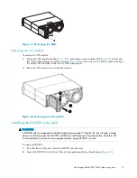
25206a
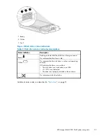
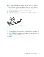
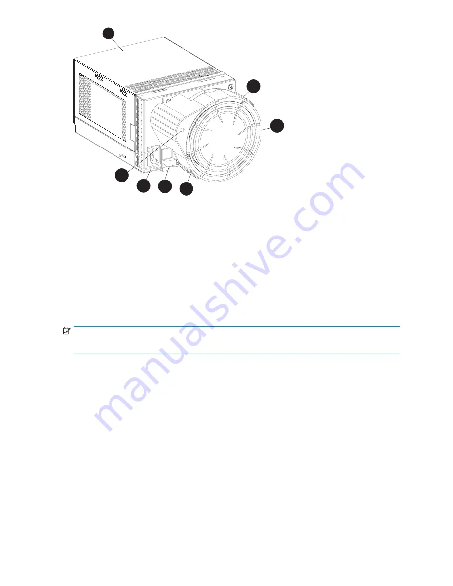
Figure 6 Power supply and blower assembly components
1. Power supply assembly
4. Module latch
2. Status LED
5. Blower tabs (2)
3. AC input connector with bail lock
6. Blower
Features
Only one operational power supply and one operational blower are required to keep the enclosure fully
functional. However, in the event of a component failure, HP strongly recommends that a replacement is
installed as soon as possible.
NOTE:
When a power supply fails, the associated blower is disabled.
The power supply circuitry monitors input voltage, current, and temperature. If it detects an unacceptable
level of any of these elements, the status indicator turns off and an error is reported to the EMU.
The EMU uses the temperature sensor signal to adjust the speed of the blowers. If one blower fails or
spins at a reduced speed, the speed of the other blower increases to provide adequate air
fl
ow.
Power supply and blower status indicator
A green LED on the blower (
Figure 6
-2) indicates the operational status of the power supply and the
blower. If either component fails, the LED turns off and an error alarm sounds. The failing component
should be replaced as soon as possible.
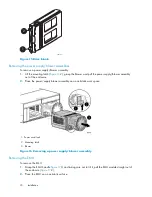
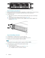
Fibre Channel disks
Up to 14 HP FC disk drives can be installed in a DS2500. Only HP-supplied FC disk drives are supported
in a DS2500.
Figure 7
shows an FC disk drive.
HP StorageWorks 2500 Disk System user guide
21
Summary of Contents for StorageWorks 2500
Page 1: ...HP StorageWorks 2500 Disk System user guide Part number 5697 6800 Second edition June 2007 ...
Page 8: ...8 ...
Page 12: ...12 About this guide ...
Page 44: ...44 Using the EMU ...
Page 54: ...54 Troubleshooting ...
Page 64: ...Figure 35 Replacing a disk drive 64 Customer self repair ...
Page 68: ...68 Specifications ...
Page 78: ...78 Regulatory notices ...


