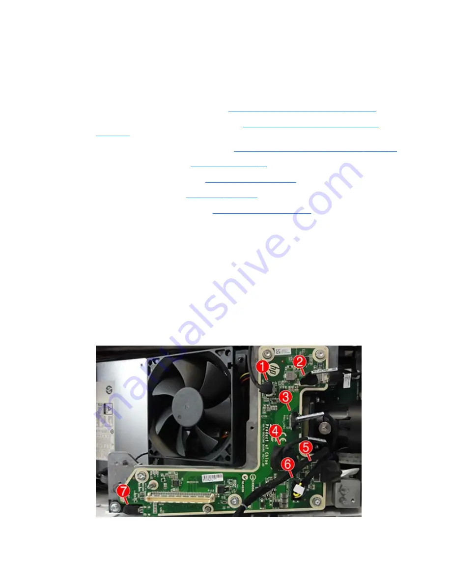
Docking board
The docking board is secured with five Torx screws. Seven cables are connected to the top of the board and
four cables are connected to the bottom of the board.
To remove the docking board:
1.
Prepare the computer for disassembly (see
Preparing to disassemble the column on page 77
).
2.
Remove the rear covers from the computer (see
Removing the rear covers from the computer
on page 78
).
3.
Separate the computer from the column (see
Separating the computer from the column on page 80
).
4.
Remove the bottom cover (see
Bottom cover on page 83
).
5.
Remove the side and top cover (see
Side and top cover on page 84
).
6.
Remove the inside cover (see
Inside cover on page 87
).
7.
Remove the docking board shield (see
Docking board shield on page 89
).
8.
Disconnect the following cables:
(1):
NFC Touchmat
(2):
Lamp
(3):
Projector
(4):
Projector power
(5):
Hi-res camera
(6):
Main power
(7):
HDMI
ENWW
Docking board
91
Summary of Contents for Sprout
Page 1: ...Maintenance Service Guide Sprout Business PC ...
Page 4: ...iv About This Book ENWW ...
Page 10: ...x ENWW ...
Page 20: ...10 Chapter 1 Getting to know your Sprout ENWW ...
Page 34: ...24 Chapter 3 Disassembly preparation and SATA drive guidelines ENWW ...
Page 86: ...76 Chapter 4 Removal and Replacement Procedures Computer ENWW ...
Page 116: ...106 Chapter 5 Removal and Replacement Procedures Column ENWW ...
Page 128: ...118 Chapter 6 Computer Setup F10 Utility ENWW ...
Page 138: ...128 Chapter 8 Troubleshooting ENWW ...
Page 158: ...148 Chapter 11 Password security and resetting CMOS ENWW ...
Page 162: ...152 Chapter 12 Maintaining peak performance ENWW ...
Page 168: ...158 Appendix C Specifications ENWW ...
Page 172: ...WLAN module illustrated 12 removing 49 162 Index ENWW ...


