background image

9-3

Diagnostics

Reboot Switch

Click 

Apply

 to save any changes for the current boot session; the changes take effect immediately.

Reboot Switch

Use this feature to perform a software reboot of the switch. If you applied configuration changes, wait 
at least one minute before rebooting to ensure that the changes are saved to the system configuration 
file.

To display the Reboot Switch page, click 

Diagnostics > Reboot Switch

.

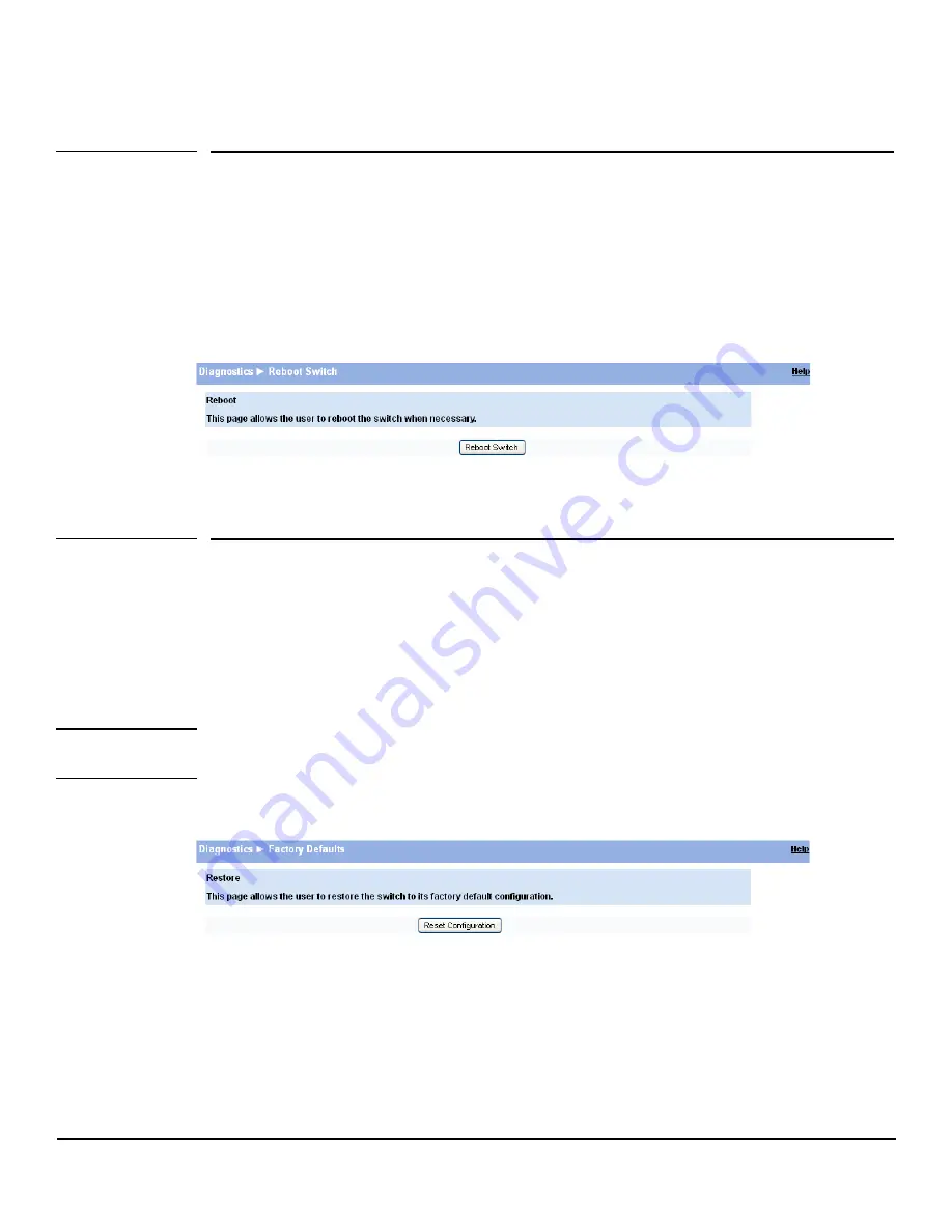
Figure 9-3. Reboot Switch Page

Click 

Reboot Switch

 to reboot the switch.

Factory Defaults

Two configuration files are kept in system memory: one contains custom settings; the other contains 
the factory defaults. Use this page to restore all settings to the factory defaults. 

To display the Factory Defaults page, click 

Diagnostics > Factory Defaults

.

C a u t i o n

Backup the current configuration file prior to restoring the factory defaults configuration. See 

“Backup 

Manager” on page 10-1

 for instructions.

Figure 9-4. Factory Defaults Page 

Click 

Reset Configuration


to reset the system to its default settings for everything except the IP settings.

Summary of Contents for PS1810 SERIES

Page 1: ...HP PS1810 Switches Management and Configuration Guide ...

Page 2: ......

Page 3: ...i HP PS1810 Switches Management and Configuration Guide June 2013 ...

Page 4: ...dification made from the original source code To receive the CD HP charges a small fee in order to cover the actual costs of manufacturing and shipping the CD The request must be sent via email to Hpn gpl hp com The modified GPL license can be found at ecos sourceware org The information contained herein is subject to change without notice Note The eCossoftware distribution also contains other sof...

Page 5: ...porting a network using HP PS1810 series switch software An understanding of the software specifications for the networking device platform and a basic knowledge of Ethernet and networking concepts are presumed About Your Switch Manual Set The switch manual set includes the following Quick Setup Guide a printed guide shipped with your switch Provides illustrations for basic installation and setup ...

Page 6: ...1 MAC table 8 k SNTP server configuration 1 Time zones count 90 Daylight Saving Time offset 1 min 1440 min Maximum servers supported 10 Maximum servers discovered 100 Jumbo frame size 9216 bytes Soft session HTTPS timeout 1 min 60 min Hard session HTTPS timeout 1 Hr 168 Hrs HTTPS sessions 5 Trunk configuration PS1810 24G PS1810 8G 12 4 Trunk membership ports PS1810 24G PS1810 8G 8 7 VLANs 64 Maxim...

Page 7: ...ogging On 1 3 Interface Layout and Features 1 3 Common Page Elements 1 4 Saving Changes 1 5 User Defined Fields 1 5 Web Applet 1 5 System LEDs 1 5 2 Status System Description 2 1 Log 2 3 Port Summary 2 5 LLDP Statistics 2 7 Trunk 2 9 MAC Table 2 10 Loop Protection 2 11 Spanning Tree 2 12 Green Features 2 14 Dual Image 2 16 Clock 2 17 3 Network Setup Get Connected 3 1 Simple Network Time Protocol 3...

Page 8: ...e Hellman Files 5 4 Generating Certificates 5 5 6 Trunks Trunk Configuration and Membership 6 1 Example Creating a Trunk 6 3 7 Virtual LAN VLAN Configuration 7 1 VLAN Ports 7 2 VLAN Participation Tagging 7 3 Advanced Configuration 7 4 8 Link Layer Discovery Protocol LLDP LLDP Configuration 8 1 LLDP Local Device 8 3 LLDP Remote Device 8 4 Energy Efficient Ethernet 8 5 9 Diagnostics Ping Test 9 1 Lo...

Page 9: ...uration File 10 2 Update Manager 10 4 Example Updating the Switch Software 10 5 Password Manager 10 8 Dual Image Configuration 10 9 11 Servers Monitor Servers 11 1 Select Server from Discovered List 11 2 Add Servers Manually 11 3 Example Adding a Server Manually 11 3 ...

Page 10: ...viii ...

Page 11: ...gement PC or to the network using any of the available network ports 2 Power on the switch 3 Set the IP address of the management PC s network adaptor to be in the same subnet as the switch Example Set it to IP address 192 168 2 12 mask 255 255 255 0 4 Enter the IP address shown above in the Web browser See page 1 3 for web browser requirements Thereafter use the Web interface to configure a diffe...

Page 12: ...lowing operating systems and browsers with JavaScript enabled are supported Operating System Browser Windows XP SP3 Firefox 6 7 19 20 Internet Explorer 7 8 Google Chrome 13 14 25 Windows 7 Firefox 6 7 19 20 Internet Explorer 8 9 10 Google Chrome 13 14 25 MacOS Firefox 6 7 18 19 Google Chrome 13 14 25 ...

Page 13: ...e switch in the Web browser address field The default IP address is 192 168 2 10 This address is used if DHCP is unable to configure the server address For more information see Get Connected on page 3 1 2 On the Login page enter the password if one has been set and then click Login By default there is no password After the initial log on the administrator may configure a password Note To set passw...

Page 14: ...formation The Web Applet displays summary information for the switch LEDs and port status in a graphical format For information on the Web Applet see Web Applet on page 1 5 Common Page Elements Click Help on each page to display a help panel that explains the fields and configuration options on the page Click to send the updated configuration to the switch Configuration changes take effect immedia...

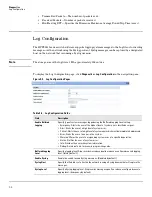
Page 15: ...ide information regarding the status parameters of individual ports The Web Applet enables easy system configuration and Web based navigation Figure 1 3 Web Applet PortConfigurationandSummary Youcan pointto any portto display the followinginformationabout the port Auto Negotiation Status Speed Left click a port to display its PortConfiguration page or right click and selectfrom the menu to display...

Page 16: ... available on PoE In port Port LEDs Each 10 100 1000 Mbps RJ45 port has two single color LEDs to indicate the Link Activity on the Left port LED and the Speed status indicated by the Right port LED The left port LED indicates link status as follows On The port is enabled and receiving a link indication or other signal from the connected device Blinking The port has network activity Off The port ha...

Page 17: ...tch type Gigabit Ethernet or a Fast Ethernet The software and boot ROM versions are also displayed In addition the system name location and contact can be configured on this page This page is displayed when you first log on or when you click Home or Status System Description in the navigation pane Figure 2 1 System Description Page Click Apply to save any changes for the current boot session the c...

Page 18: ...location of this switch A maximum of 31 alpha numeric characters including hyphens commas and spaces are allowed This field is blank by default System Contact Enter the name of the contact person for this switch A maximum of 31 alpha numeric characters including hyphens commas and spacesare allowed Thisfield is blank by default Software Version The version of the code running on the switch in the ...

Page 19: ...0 log entries were generated since the system was last restarted or the log file was cleared then the log file would display entries 101 200 To display the Log status page click Status Log in the navigation pane Figure 2 2 Log Page Click the arrows next to the column headings to sort the list by the column in ascending or descending order Click Clear to delete all log messages Click the Refresh li...

Page 20: ...tion on page 9 2 Log Message Log Index Log number in the log table Severity Severity associated with the log message Log Time Time at which the log was entered in the table Component Component from which the massage was logged Description Description of the entry Field Description ...

Page 21: ...he last clear operation Refreshing the page shows the latest statistics which provide per port statistics on packets transmitted and received for all the ports Scroll down the page to view the Port Statistics table which provides per port statistics on packets transmitted and received To display the Port Summary page click Status Port Summary in the navigation pane A configuration summary and stat...

Page 22: ...eptable on the specified port Port Statistics and Trunk Statistics Note The following statistics are collected for both individual port and for trunks Interface Trunk List of physical and logical interfaces supported on that platform Received Packets w o Error The packet count received on the port with out any packet errors Received Packets with Error The packet count received on the port with err...

Page 23: ...r Discovery Protocol LLDP Statistics page displays summary and per port information for LLDP frames transmitted and received on the switch To display the LLDP Statistics page click Status LLDP Statistics in the navigation pane Figure 2 4 LLDP Statistics Page ...

Page 24: ... into tables associated with the remote systems because of insufficient resources Age Outs The number of times the complete set of information advertised by a particular MAC Service Access Point MSAP has been deleted from tables associated with the remote systems because the information timeliness interval has expired Time Since Last Update Time when an entry was created modified or deleted in the...

Page 25: ...gation Control Protocol Data Units LACPDUs with links in the trunk The PDUs contain information about each link and enable the trunk to maintain them Static trunks are assigned to a bundle by the administrator Members do not exchange LACPDUs A static trunk does not require a partner system to be able to aggregate its member ports Admin Status Displays whether the trunk has been enabled or disabled...

Page 26: ...C Table Page Table 2 6 MAC Table Fields Click the Refresh link above the page to re display the page with current data from the switch Field Description MaximumEntries Supported Displays a maximum of 8192 MAC address entries that can be learned on the switch Current Entries Displays the number of MAC address entries currently learned MAC Address The list of MAC addresses learned on a particular in...

Page 27: ...iption Interface List of ports with loop protection currently enabled Configured Action Taken The action that is set to occur when a loop is detected on the port with Loop Protection enabled Shutdown port The port will be shut down for the configured period Log The event will be logged and the port remains operational Shutdown and log The event will be logged and the port it shut down for the conf...

Page 28: ...ng Tree Bridge Status Spanning Tree The current operational state of the bridge enabled or disabled Spanning Tree Version The current protocol version of the bridge STP or RSTP Switch MAC Address MAC address of the switch Switch Priority The configured spanning tree priority of the switch Max Age The current Max Age bridge parameter setting Forward Delay The current Forward Delay bridge parameter ...

Page 29: ...nthisbridge theBackup port is a port on this bridge that can become the Designated port if needed DisabledPort Not strictly part of the Spanning Tree protocol a network administrator can manually disable the port State The current Spanning Tree port state The port state can be one of the following values Blocking A port that may cause a switching loop no user data is sent or received but it may go...

Page 30: ... Green Features The Green Features status page displays the status of the power saving or green features To display the Green Features page click Status Green Features in the navigation bar Figure 2 9 Green Features Status Page ...

Page 31: ...d or Disabled that indicates if the switch is configured to change LED intensity levels at certain times of day Intensity Level The desired LED intensity level that takes effect if the LED Intensity setting is enabled Valid values are High Medium Low or Off Default value is Off Start Time The time of day when the configured LED Intensity Level is activated Duration The number of hours the configur...

Page 32: ... Table 2 10 Dual Image Status Fields For instructions on configuring the active image see Dual Image Configuration on page 10 9 Field Description Active The currently active image name Next Active The next active image name The administrator can configure the image to take effect the next time the system is booted It may be a different than the currently active image for example if the administrat...

Page 33: ... system time increments from 00 00 00 1 Jan 1970 which is set at bootup Date The current date Time Source Source from which the time and date is obtained Time Zone Time Zone The currently set time zone Acronym The acronym configured on the system for the time zone e g PST EDT Daylight Savings Time Daylight Savings Time Shows whether Daylight Savings Time is enabled and the mode of operation Enable...

Page 34: ...2 18 Status Clock ...

Page 35: ... can be selected as the management port for the network interface The configuration parameters associated with the switch s network interface do not affect the configuration of the front panel ports through which traffic is switched or forwarded except that for the management port the PVID will be the management VLAN To display the Get Connected page click Network Setup Get Connected As shown in t...

Page 36: ...uch cases you may fail to connect after maximum sessions are left open indefinitely Management Access Management VLAN ID Access tothe managementsoftware is controlledbythe assignmentofaVLANID Bydefault the management VLAN ID is 1 The allowed range is 2 to 4094 All ports are members of VLAN 1 by default the administrator may want to create a different VLAN to assign as the management VLAN and assoc...

Page 37: ...IP address to its factory default value A manual reset to factory defaults is the only way to access a switch without the IP address Community Name Specify a community name or use the default name public The switch supports the following MIBs BRIDGE MIB IEEE 802 1Q LLDP MIB IEEE 802 3AB EtherLike MIB IF MIB RFC1213 MIB RMON MIB RMON History as in v1 Field Description ...

Page 38: ...The software operates only as an SNTP client and cannot provide time services to other systems The SNTP server port of 123 is used by default A log message is generated when the configured SNTP server is unreachable Note SNTP acquires the Coordinated Universal Time UTC from an SNTP server Configure the Time Zone see page 3 6 and Daylight Saving Time see page 3 7 to configure the offsets for your l...

Page 39: ...d thesystem time increments from 00 00 00 1 Jan 1970 which is set at bootup SNTP NTP Server Specify the IP address of the SNTP server to send requests to Server Port Specify the server s UDP port to listen for responses broadcasts range 1 65535 default 123 Time Format Select either 24 hour military time format or 12 hour standard format Last Update Last update date and time UTC assigned by this se...

Page 40: ...3 Time Zone Page Table 3 3 Time Zone Fields Click Apply to save any changes for the current boot session the changes take effect immediately Click the Refresh link above the page to re display the page with current settings from the switch To view a summary of clock and time zone information click Status Clock in the navigation pane Field Description Time Zone Select the time zone for your locatio...

Page 41: ...When configured the system time will adjust automatically during Daylight Saving Time To display the Daylight Saving Time page click Network Setup Daylight Saving Time in the navigation pane The page displays differently depending on the mode selected in the Daylight Saving Time field In the following figure the mode is set to Recurring Figure 3 4 Daylight Saving Time Page ...

Page 42: ...g to indicate when the change to DST occurs and when it ends When Recurring is selected as the DST mode the following fields display Week Set the week of the month from 1 to 5 when the change to from DST occurs Day Set the day of the week when the change to from DST occurs Month Set the month when the change to from DST occurs Hours Set the hour of the day when the change to from DST occurs Minute...

Page 43: ...IC fiber transceivers are used the link speed can be configured as 100 1000Mbps Full Duplex depending on the transceiver capability Auto Detect and Configure Fiber Modules The auto detect and configure feature detects the type of fiber module inserted in a fiber port and automatically configures it with the appropriate settings When a fiber module is inserted or changed the link speed menu shows t...

Page 44: ...pane Figure 4 2 Jumbo Frames Page Table 4 2 Jumbo Frames Fields Click Apply to save any changes for the current boot session the changes take effect immediately Field Description Interface Select the interface to configure Physical Type Describes the port type i e Copper or Fiber Link Status Displays Up or Down to indicate operational status Admin Mode Enable access to the port on the network Clea...

Page 45: ... its default state the destination port does not participate in traffic forwarding and it cannot be configured to participate in VLANs Caution When configuring port mirroring avoid oversubscribing the destination port to prevent the loss of mirrored data While a port is used as the destination port for mirrored data the port cannot be used for any other purpose the port will not receive and forwar...

Page 46: ...port selectthedirectionofthepackets to be mirrored Tx and Rx All packets transmitted and received on the source port are mirrored Rx Only packets received on the source port are mirrored Tx Only packets transmitted on the source port are mirrored None No packets are mirrored from this port default The port selected as the Destination Port is greyed out and unavailable for selection Ports that are ...

Page 47: ...is auto negotiated Use the Flow Control page to enable or disable this functionality It is disabled by default and can be configured globally across all the ports To display the Flow Control page click Switching Flow Control in the navigation pane As shown in the example configuration in Figure 4 4 flow control is enabled globally which would enable flow control on all the ports in the switch Figu...

Page 48: ...lows the user to enable or disable port cable and LED energy saving features that consume less power than the normal high performance mode To display the Green Features configuration page click Switching Green Features in the navigation pane Figure 4 5 Green Features ...

Page 49: ...e Length Detect Enable port power consumption based upon the cable length such that shorter cables use less power This feature is disabled by default LED intensity Configuration LED Intensity Enable LED intensity control globally on all ports Intensity Level SetsthedesiredLEDintensitylevel ValidvaluesareHigh Medium Low andOff DefaultvalueisOff Start Time Specifies the time of day when the configur...

Page 50: ... on all the ports on which the feature is enabled Transmission of the packet can be disabled selectively on certain ports even when Loop Protection is enabled If this multicast packet comes back to the switch with any of the ports MAC addresses as the source the switch determines that a loop has occurred The port that received the loop protection packet from the switch can be shut down for a confi...

Page 51: ...ll Enables all interfaces with Loop Protection One by One Enables you to configure Loop Protection on ports individually default None Disables Loop Protection on all interfaces Interface Loop Protection Select Enable for each port on which you want to use this feature Action If Loop Protection is enabled on a port select one of the following actions to occur when a loop is detected Log The event i...

Page 52: ...display the Spanning Tree configuration page click Switching Spanning Tree in the navigation pane Figure 4 7 Spanning Tree Table 4 7 Spanning Tree Fields Field Description Spanning Tree Bridge Configuration Protocol Mode Enable the Spanning Tree protocol mode globally This feature is disabled by default Protocol Version Specify the protocol RSTP or STP RSTP is set by default Bridge Priority Specif...

Page 53: ...h identical port costs The default is 128 64 for trunk ports Admin Edge Configure the port to act as a non edge or edge port for Spanning Tree The default is non edge Auto Edge Enable automatic edge port detection for the port Root Guard Whenrootguardisenabledonaport thatportcannotbeselectedastherootportevenifitreceives superior STP BPDUs The port is assigned an alternate port role and enters a bl...

Page 54: ...4 12 Switching Spanning Tree ...

Page 55: ...rol protection for unicast broadcast and multicast traffic The traffic is dropped if the rate of incoming traffic on an interface increases beyond the threshold of 64K pps Auto Denial of Service DoS protections A DoS attack is an attempt to saturate the switch with external communication requests to prevent the switch from performing efficiently or at all You can enable Auto DoS protection that pr...

Page 56: ...ng it against its own list of CAs Web browsers such as Microsoft Internet Explorer and Mozilla Firefox maintain data on trusted CAs After validating the CA the browser and switch negotiate the highest level of security available to both The browser uses the public key to encrypt a random number and send it to the switch The switch uses a private key stored in memory not advertised on the certifica...

Page 57: ...nge the timeout settings click Apply to save the changes for the current boot session the changes take effect immediately Note Download or regenerate a certificate when the previous certificate has expired or when you have reason to suspect that security has been breached and the certificate has been taken for use by another server Field Description HTTP Admin Mode Enable the Administrative mode o...

Page 58: ...For a TFTP upload enter the Server IP address and specify the File Path and File Name 4 From the Update Type field on the File Download page select one of the following SSL Trusted Root Certificate PEM File SSL Trusted Root Certificate File PEM Encoded An SSL certificate that has been digitally signed by a certificate authority SSL Server Certificate PEM File SSL Server Certificate File PEM Encode...

Page 59: ... refreshes with the message Certificate has been generated 2 Click Apply to complete the process When the process is complete the page refreshes with the message No certificate generation in progress and the Certificate Present field displays as True When a certificate is present a Delete button appears to enable deleting the certificate ...

Page 60: ...5 6 Security Secure Connection ...

Page 61: ...Control Protocol Data Units LACPDUs with links in the trunk The PDUs contain information about each link and enable the trunk to maintain them Static trunks are assigned to a group by the administrator Members do not exchange LACPDUs A static trunk does not require a partner system to be able to aggregate its member ports All members of a trunk must be either static or dynamic Note Most servers re...

Page 62: ... traffic will flow and LACPDUs will be dropped The links that form the trunk will not be released Static Trunk is enabled in static mode A static trunk interface does not require a partner system to be able to aggregate its member ports In this mode it does not transmit or process received LACPDUs Member ports do not transmit LACPDUs and all the LACPDU received are dropped LACP Active Trunk will b...

Page 63: ...iately Example Creating a Trunk Follow these instructions to set up a trunk and manually add port members using the Static mode 1 Click Trunk Trunk Configuration in the navigation pane to display the Trunk Configuration page Figure 6 2 Trunk Configuration Page 2 In the Name field enter a name for the new trunk you wish to set up Figure 6 3 Trunk Name 3 Use the Mode drop down list to select a mode ...

Page 64: ...6 4 Trunks Trunk Configuration and Membership Figure 6 4 Trunk Mode 4 Select ports to add them to the trunk Figure 6 5 Trunk Ports 5 Click Apply to set up a trunk with the selected port members ...

Page 65: ...which it is connected both belong to the same VLAN Each VLAN in a network has an associated VLAN ID which displays in the IEEE 802 1Q tag in the Layer 2 header of packets transmitted on a VLAN An end station may omit the tag or the VLAN portion of the tag in which case the first switch port to receive the packet may either reject it or insert a tag using its default VLAN ID A given port may handle...

Page 66: ...delete a VLAN select Delete VLAN and click Apply The default VLAN cannot be deleted To specify a VLAN name select Set Name type a name in the VLAN Name field and click Apply A VLAN name can have any case sensitive combination of up to 32 alpha numeric characters and can contain _ and a z A Z 0 9 _ and Field Description Interface Select the port on which to configure the VLAN settings PVID The VLAN...

Page 67: ... the tagging policy for outgoing packets on a port or trunk Note All ports are members of VLAN1 by default Each port must be a member of at least one VLAN An error message is displayed if a user attempts to exclude a port from participation in its only VLAN Ports belonging to a trunk cannot be assigned membership in a VLAN although the trunk itself can be a member of one or more VLANs When a membe...

Page 68: ... the servers in non native subnets for consolidated management To display the Advanced Configuration page click VLANs Advanced Configuration in the navigation pane Field Description VLAN Select the VLAN to configure Tag Untag Exclude All ForaportortrunktoparticipateinaVLAN itstaggingpolicymustbedefined Bydefault all ports and trunks are configured as untagged members of VLAN1 and are excluded from...

Page 69: ...mmediately Field Description Management VLAN ID ID of the management VLAN IP Address IP address of the management VLAN Subnet Mask Subnet mask of the management VLAN VLAN ID Select a VLAN ID All created VLANs are displayed in this list IP Address Enter an IP address for the selected VLAN Subnet Mask Enter the subnet mask for the selected VLAN Clear Clear the VLAN ID details ...

Page 70: ...7 6 Virtual LAN Advanced Configuration ...

Page 71: ...ations implementing the transmit function and is received and processed by stations implementing the receive function The transmit and receive functions can be enabled disabled separately per port By default both transmit and receive are enabled on all ports The application is responsible for starting each transmit and receive state machine appropriately based on the configured status and operatio...

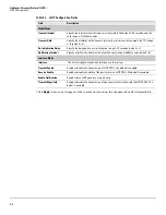
Page 72: ...ult 4 Re Initialization Delay Specify the delay before a re initialization range 1 10 seconds default 2 Notification Interval Specify a limit for the transmission of notifications range 5 3600 seconds default 5 Interface Mode Interface The list of all physical and trunk interfaces on the system Transmit Enable Enable or disable the transmission of LLDP PDUs The default is enabled Receive Enable En...

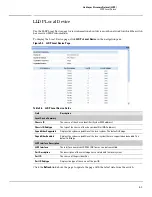
Page 73: ...e Summary Chassis ID The source of the chassis identifier System MAC address Chassis ID Subtype The type of the source of the chassis identifier MAC address Capabilities Supported Displays the system capabilities of the local system The default is Bridge Capabilities Enabled Displays the system capabilities of the local system that are supported and enabled The default is Bridge LLDP Interface Des...

Page 74: ...tings from the switch Field Description Local Interface The port on the local system that received the LLDP data from the remote system Chassis ID The chassis component associated with the remote system Port ID The physical address of the port on the remote device that sent the LLDP data Port Description The port description configured on the remote device If the port description is not configured...

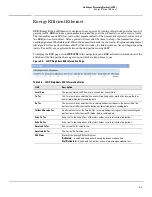
Page 75: ...to use Figure 8 4 LLDP Neighbors EEE Information Page Table 8 4 LLDP Neighbors EEE Information Fields Field Description Local Port The port on which LLDP frames are received or transmitted Tx Tw The time in microseconds that the transmitting link partner waits after leaving the low power idle mode before sending data Rx Tw The time in microseconds that the receiving link partner requests the trans...

Page 76: ...8 6 Link Layer Discovery Protocol LLDP Energy Efficient Ethernet ...

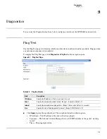
Page 77: ... Table 9 1 Ping Test Fields Click Apply to ping the specified host The output includes the following data IP Address The IP address of the device that was pinged Sequence The Internet Control Message Protocol ICMP number of the packet starting from 0 Time The ping reply status Field Description IP Address Specify the IP address of the host you want to reach Count Specify the number of packets to s...

Page 78: ... using the Buffered Logging Level setting Emergency Alerts the user of the highest level of system error classified as urgent Alert Alerts the user of a high level of system error Critical Alertstheuserofahigh level ofsystemerrorwhich mustbe immediately addressed Error Alerts the user of an error in the system Warning Warns the user of an impending system error of a specified operation Notice Noti...

Page 79: ... 9 3 Reboot Switch Page Click Reboot Switch to reboot the switch Factory Defaults Two configuration files are kept in system memory one contains custom settings the other contains the factory defaults Use this page to restore all settings to the factory defaults To display the Factory Defaults page click Diagnostics Factory Defaults Caution Backup the current configuration file prior to restoring ...

Page 80: ...gnostics Support File in the navigation pane Figure 9 5 Support File Page The support file page includes the following information System description Monitored servers Dual image status Buffered log messages Logging configuration SNTP configuration Time zone configuration IP configuration Port configuration summary and statistics Trunk statistics Jumbo frames configuration ...

Page 81: ...d bottom of the page You can print the text from your text editor Alternatively your browser may support printing only the frame that contains the data that is it excludes the navigation pane and Web Applet directly from the Web page Right click the data area to see if your browser provides this option Locator The Locator LED is a special LED on the HP PS1810 24G that enables locating the device p...

Page 82: ...9 6 Diagnostics Locator ...

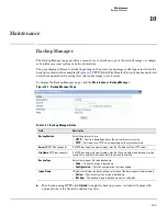
Page 83: ...p process A window displays with a prompt to save the file in the desired location Field Description Backup Method Select the protocol to use HTTP The file is downloaded over the current browser session TFTP This requires a TFTP server operating on the system network Server IP TFTP backup only If a TFTP backup is to be performed enter the IP address of the TFTP server File Name TFTP backup only If...

Page 84: ...ect Do not save encrypted pages to disk 3 Try the backup operation again 4 After the backup operation is complete restore your settings to the original values to avoid Web performance issues If you use a browser other than Microsoft Internet Explorer such as Firefox or Mozilla the download of the attachment should work as expected Example Backing Up a Configuration File Follow these instructions t...

Page 85: ... in progress When the backup is complete a confirmation is displayed Figure 10 4 Backup Confirmation 6 Click OK The Backup Manager page displays the transfer status message Figure 10 5 Backup Transfer Status 7 Click Back to re display the Backup Manager page Note To restore a backed up code or configuration file use Update Manager ...

Page 86: ...the software update click Browse to select the designated file Note If the file name differs from the default name on the switch the file will be renamed to the default name when uploaded see the Update Type field description Server IP TFTP upload only If a TFTP download is performed enter the IP address of the TFTP server File Name TFTP upload only If a TFTP download is performed enter the name a...

Page 87: ...r If HTTP is selected browse to locate the file on your network or local drive 3 In the Update Type field select Code 4 In the Image field choose Backup or Active If you choose Backup the inactive backup image file will be updated In the example in Figure 10 6 on page 10 4 the Backup image file is selected for update If you choose Active the active image file will be updated 5 Click Download A war...

Page 88: ...s Figure 10 9 Backup Transfer Status Caution Do not disturb the browser window while the transfer is in progress A message is displayed to confirm that the switch will be rebooted immediately to use the new configuration Figure 10 10 Reboot Confirmation When the update is complete a confirmation is displayed ...

Page 89: ...te that in this example the image was downloaded as the inactive backup image To complete the update process and to activate the backup image as the operating software use the Dual Image Configuration page In the following example Image1 is the active image and Image2 is the newly updated backup image By clicking Activate Image2 will be activated on the next reboot and Image1 will become the inact...

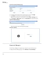
Page 90: ...ify the next active image by viewing the Status Dual Image screen 12 Click Diagnostics Reboot Switch and then click Reboot Switch to complete the update Figure 10 14 Reboot Switch Page Wait for the switch to reboot and display the login page Figure 10 15 Login Page Password Manager Use the Password Manager to change the password used to access the Web interface To display the Password Manager page...

Page 91: ...otup image The Dual Image Configuration allows activating either of the stored images Image1 or Image2 When one image is activated the other image serves as a backup if Image1 either fails or does not boot then the other image can be activated To display the Dual Image Configuration page click Maintenance Dual Image Configuration Figure 10 17 Dual Image Configuration Page Table 10 3 Dual Image Con...

Page 92: ...age Description field to the version of the image loaded so that users can easily distinguish between the images Click Apply to apply a description to the image selected in the Image Name field Click Delete to delete the image selected in the Image Name field To view dual image status information click Status Dual Image Status in the navigation pane ...

Page 93: ...ontrol capabilities that can be used to diagnose OS or server problems remotely You can use the Monitor Servers page to monitor and add iLO enabled servers which send periodic status updates to the HP PS1810 series switch Monitor Servers The Monitor Servers page provides a dashboard like interface to monitor and add servers To display the Monitor Servers page click Servers Monitor Servers in the n...

Page 94: ...nction Figure 11 2 Discovered Servers Options Field Description Monitored Servers Server System Health System health indicator for monitored server OK System is fully operational Degraded System is operating at a reduced capacity Failed One or more components are not operational Not Available System status cannot be ascertained Server Product Name Monitored server name A maximum of ten servers can...

Page 95: ... Add Servers Options Table 11 3 Manually Add Servers Fields Click Apply under the Add New Server to Monitored List to add the specified server Example Adding a Server Manually Follow these instructions to add a new server manually to the monitored servers list 1 Click Servers Monitor Servers in the navigation pane to display the Monitor Servers page Field Description Discovered Servers Server Prod...

Page 96: ...nitor Servers Page 2 Use the Add Server drop down list to select the Manually option for adding a server Figure 11 5 Server Add Method 3 Enter the IP address of the server to be added in the Server IP Address field Figure 11 6 Server IP Address ...

Page 97: ...11 5 Servers Monitor Servers 4 Click Apply to add the server manually to the Monitored Servers list Figure 11 7 Monitored Servers ...

Page 98: ...11 6 Servers Monitor Servers ...

Page 99: ......

Page 100: ...is subject to change without notice The only warranties for HP products and services are set forth in the express warranty statements accompanying such products and services Nothing herein should be construed as constituting an additional warranty HP will not be liable for technical or editorial errors or omissions contained herein June 2013 Manual Part Number 5998 4314 ...

Reviews: