Hardware Options Installation
4.
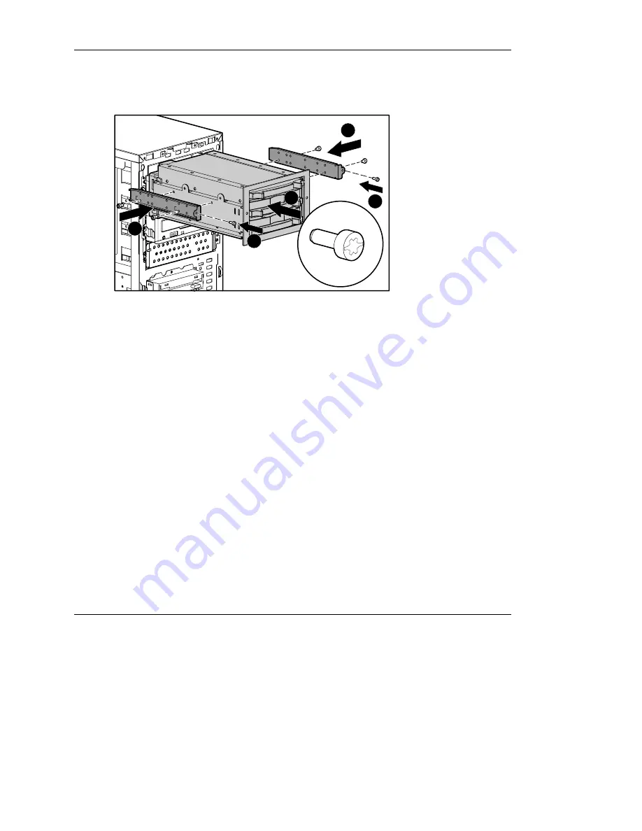
Position the rails and two guide screws in the lower mounting holes on each side
of the drive cage and tighten the screws (1).
CAGE
CAGE
L
2
1
3
1
3
Figure 3-20: Attaching the rails to the drive cage
5.
Insert the SCSI cable that ships with the drive cage option kit into the rear of the
removable media bay area, and then pull it forward for connection to the SCSI
connector on the back of the drive cage.
6.
Locate the power cable inside the server and connect it to the power connector on
the back of the drive cage. Refer to “Cabling a Two-Bay Hot-Plug SCSI Drive
Cage” in Chapter 4 for more information.
IMPORTANT: Always use the SCSI cable that ships with the drive cage option kit. Other
available SCSI cables may not support Ultra3 SCSI.
7.
Slide the drive cage into the removable media bay until it locks into place (2).
8.
Screw the ends of the rails into the chassis on both sides (3).
9.
Connect the other end of the SCSI cable to the desired internal SCSI connector.
Refer to the HP Internal Two-Bay Hot-Plug SCSI Drive Cage Installation
Instructions for additional information.
HP ProLiant ML310 Server Setup and Installation Guide
3-23
HP CONFIDENTIAL
Writer: Ted Weiman File Name: d-ch3.doc
Codename: Son of Beast Part Number: 274431-002 Last Saved On: 11/22/02 1:58 PM


