Hardware options installation 82
b.
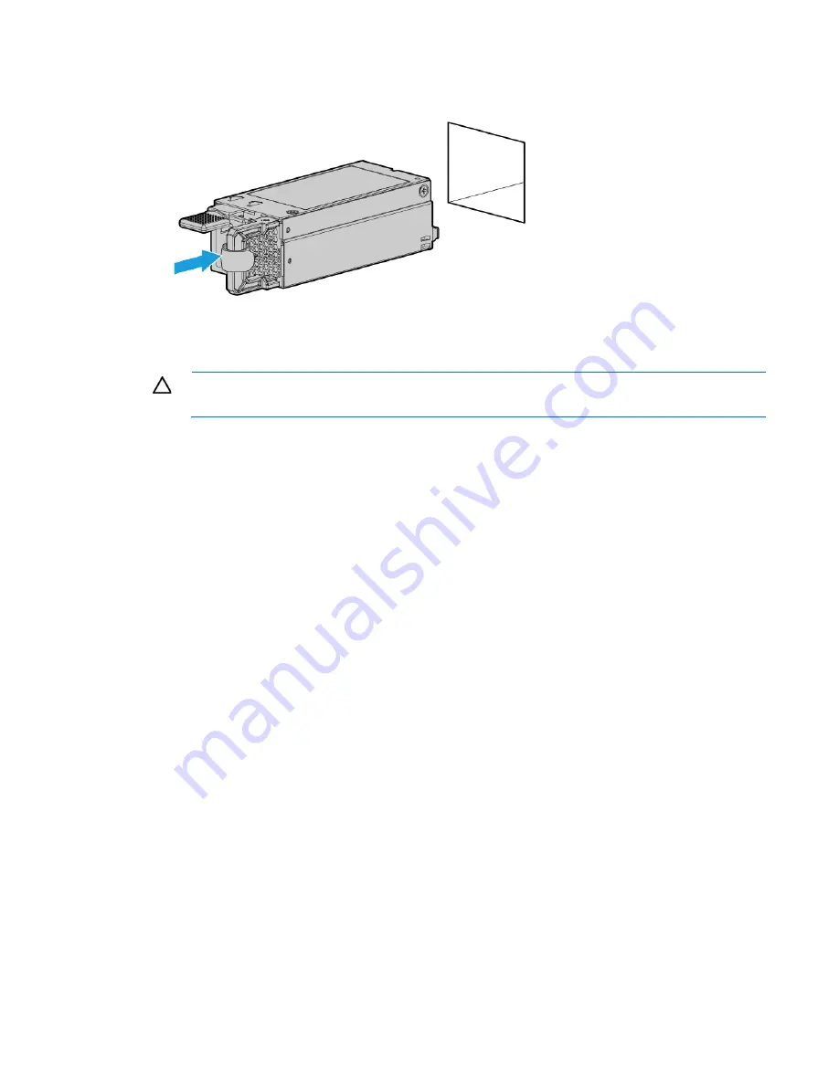
Install a hot-plug power input module into power supply bay 2.
11.
Reconnect all server cables that were disconnected to access the removed power supply.
12.
Reinstall all server components that were removed to access the removed power supply.
CAUTION:
To prevent improper cooling and thermal damage, do not operate the server unless
all bays are populated with either a component or a blank.
13.
Install the access panel (on page
22
).
14.
Do one of the following:
o
Slide the server into the rack.
o
Install the server into the rack ("
Installing the server into the rack
" on page
30
).
15.
Power up the server (on page
17
).
Dedicated iLO management module option
For more information about product features, specifications, options, configurations, and compatibility, see
the product QuickSpecs on the HP website (
http://www.hp.com/go/qs
).
To install the component:
1.
Power down the server (on page
17
).
2.
Remove all power:
a.
Disconnect each power cord from the power source.
b.
Disconnect each power cord from the server.
3.
Do one of the following:
o
Extend the server from the rack (on page
17
).
o
Remove the server from the rack (on page
20
).
4.
Remove the access panel (on page
21
).
5.
Remove the PCI riser cage (on page
23
).
Summary of Contents for ProLiant DL160 Gen9
Page 92: ...Cabling 92 M 2 SSD cabling Slot 1 cable routing Slot 2 cable routing ...
Page 94: ...Cabling 94 FBWC module slot 2 cabling FBWC module slot 3 cabling ...
Page 95: ...Cabling 95 HP Smart Storage Battery cabling FlexibleLOM cabling ...
Page 99: ...Cabling 99 Front USB 3 0 cabling ...
Page 129: ...Support and other resources 129 ...
Page 130: ...Support and other resources 130 ...


