background image

Item

Component

Spare part number

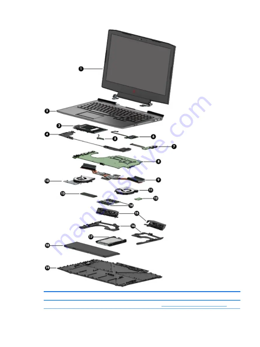
(1)

Display assembly: For display assembly spare part information, see 

Display assembly subcomponents on page 24

.

Computer major components

19

Summary of Contents for OMEN 15-ce100

Page 1: ...OMEN by HP 15 Notebook PC Maintenance and Service Guide ...

Page 2: ...1980 003 Product notice This user guide describes features that are common to most models Some features may not be available on your computer Not all features are available in all editions of Windows This computer may require upgraded and or separately purchased hardware drivers and or software to take full advantage of Windows functionality Go to http www microsoft com for details In accordance w...

Page 3: ...s that should only be accessed by an authorized service provider See Chapter 5 Removal and replacement procedures for Customer Self Repair parts for details Accessing parts described in Chapter 6 Removal and replacement procedures for authorized service provider parts can damage the computer or void your warranty iii ...

Page 4: ...iv Important Notice about Customer Self Repair Parts ...

Page 5: ...w another hard surface such as an adjoining optional printer or a soft surface such as pillows or rugs or clothing to block airflow Also do not allow the AC adapter to contact the skin or a soft surface such as pillows or rugs or clothing during operation The device and the AC adapter comply with the user accessible surface temperature limits defined by the International Standard for Safety of Inf...

Page 6: ...vi Safety warning notice ...

Page 7: ... Display assembly subcomponents 24 Miscellaneous parts 25 4 Removal and replacement procedures preliminary requirements 26 Tools required 26 Service considerations 26 Plastic parts 26 Cables and connectors 27 Drive handling 27 Grounding guidelines 28 Electrostatic discharge damage 28 Packaging and transporting guidelines 29 Workstation guidelines 29 Equipment guidelines 30 5 Removal and replacemen...

Page 8: ...ver 63 Display bezel 66 Display hinges 68 Webcam 70 Display panel 72 Display cable and webcam cable 75 WLAN antennas 77 Back cover 79 7 Using Setup Utility BIOS 80 Starting Setup Utility BIOS 80 Updating Setup Utility BIOS 80 Determining the BIOS version 80 Downloading a BIOS update 81 8 Using HP PC Hardware Diagnostics 82 Using HP PC Hardware Diagnostics Windows select products only 82 Downloadin...

Page 9: ...nloading Remote HP PC Hardware Diagnostics UEFI by product name or number 85 Customizing Remote HP PC Hardware Diagnostics UEFI settings 85 9 Backing up restoring and recovering 87 Backing up information and creating recovery media 87 Using Windows tools 87 Using the HP Cloud Recovery Download Tool to create recovery media select products only 87 Restoring and recovery 88 Restoring resetting and r...

Page 10: ...x ...

Page 11: ...or GPS GPU Performance Scaling Support for VR Support for MR ready Panel 15 6 in 1920 1080 FHD WLED AntiGlare typical brightness 220 nits slim 3 2 mm UWVA eDP Memory Support for 16384 MB of DDR4 2666 MHz system memory in the following configurations 16384 MB 8192 MB 2 12288 MB 8192 MB 1 4096 MB 1 8192 MB 8192 MB 1 Hard drive Support for the following single hard drive and solid state drive configu...

Page 12: ... island style keyboard with numeric key pad in Dragon Red color Full size backlit 3 coat paint island style keyboard with numeric key pad with White OMEN logo and RGB backlight TouchPad TouchPad with image sensor Multitouch gestures enabled by default Support for Modern Touchpad gestures Taps enabled by default Support for 26 key NKRO Anti Ghosting keys Power requirements 200 W Smart AC adapter us...

Page 13: ...egory Description Windows 10 Home Plus EM SL Indonesia PPP Windows 10 Home Plus EM SL APAC PPP Free DOS 2 0 Serviceability End user replaceable parts Hard drive Solid state drive Memory module AC adapter 3 ...

Page 14: ... 2 Connect USB devices such as a cell phone camera activity tracker or smartwatch and provide high speed data transfer 4 Drive light Blinking white The hard drive or the solid state drive is being accessed Amber HP 3D DriveGuard has temporarily parked the hard drive 5 Memory card reader Reads optional memory cards that enable you to store manage share or access information To insert a card 1 Hold ...

Page 15: ...ctivity is occurring on the network 5 USB SuperSpeed port with HP Sleep and Charge Connects a USB device provides high speed data transfer and even when the computer is off charges most products such as a cell phone camera activity tracker or smartwatch 6 USB Type C port with HP Sleep and Charge Connects a USB device that has a Type C connector provides high speed data transfer and even when the c...

Page 16: ...y NOTE Refer to the illustration that most closely matches your computer Component Description 1 Security cable slot Attaches an optional security cable to the computer NOTE The security cable is designed to act as a deterrent but it may not prevent the computer from being mishandled or stolen 2 Mini DisplayPort Connects an optional digital display device such as a high performance monitor or proj...

Page 17: ... headset or a television audio cable Also connects an optional headset microphone This jack does not support optional standalone microphones WARNING To reduce the risk of personal injury adjust the volume before putting on headphones earbuds or a headset For additional safety information refer to the Regulatory Safety and Environmental Notices To access this guide Select the Start button select HP...

Page 18: ...cate with wireless local area networks WLANs The antennas are not visible from the outside of the computer and antenna location varies For optimal transmission keep the areas immediately around the antennas free from obstructions For wireless regulatory notices see the section of the Regulatory Safety and Environmental Notices that applies to your country or region To access this guide 1 Type supp...

Page 19: ...ad zone Reads your finger gestures to move the pointer or activate items on the screen 2 Left TouchPad button Functions like the left button on an external mouse 3 Right TouchPad button Functions like the right button on an external mouse Keyboard area 9 ...

Page 20: ...ded components Off The computer is off or in Hibernation Hibernation is a power saving state that uses the least amount of power 2 Caps lock light On Caps lock is on which switches the key input to all capital letters 3 Mute light On Computer sound is off Off Computer sound is on 4 TouchPad light On The TouchPad is off Off The TouchPad is on 10 Chapter 2 External component identification ...

Page 21: ...omputer is in Hibernation press the button briefly to exit Hibernation CAUTION Pressing and holding down the power button results in the loss of unsaved information If the computer has stopped responding and shutdown procedures are ineffective press and hold the power button down for at least 5 seconds to turn off the computer To learn more about your power settings see your power options Right cl...

Page 22: ...quently used system functions 5 INSERT Airplane mode key also referred to as the wireless button Turns the insert mode on or off or Turns the airplane mode on or off Press and hold the key in combination with the fn key NOTE A wireless network must be set up before a wireless connection is possible 6 OMEN key Opens the OMEN Command Center software 7 END PRT SC key Turns the END mode on or off or P...

Page 23: ...ng this key alternates the screen image from the computer display to the monitor display to a simultaneous display on both the computer and the monitor Turns the keyboard backlight off or on NOTE To conserve battery power turn off this feature Mutes or restores speaker or headphone sound Decreases speaker or headphone volume incrementally while you hold down the key Increases speaker or headphone ...

Page 24: ...nable airflow to cool internal components NOTE The computer fan starts up automatically to cool internal components and prevent overheating It is normal for the internal fan to cycle on and off during routine operation 14 Chapter 2 External component identification ...

Page 25: ...back of the display or on the bottom of a tablet kickstand Service label Provides important information to identify your computer When contacting support you may be asked for the serial number the product number or the model number Locate this information before you contact support Your service label will resemble one of the examples shown below Refer to the illustration that most closely matches ...

Page 26: ...egulatory information about the computer Wireless certification label s Provide s information about optional wireless devices and the approval markings for the countries or regions in which the devices have been approved for use 16 Chapter 2 External component identification ...

Page 27: ...of the keyboard The HP OMEN Command Center dashboard provides a central location to access and configure the following features NOTE Features may vary by platform Network speed View and adjust priorities Gaming Macro Keys Configure the P keys select products only Keyboard lighting Customize the keyboard lighting OMEN Game Stream Stream your games from anywhere Update Refresh the display Help Acces...

Page 28: ...rted parts for your computer go to http partsurfer hp com select your country or region and then follow the on screen instructions NOTE Details about your computer including model serial number product key and length of warranty are on the service tag at the bottom of your computer See Labels on page 15 for details 18 Chapter 3 Illustrated parts catalog ...

Page 29: ...Item Component Spare part number 1 Display assembly For display assembly spare part information see Display assembly subcomponents on page 24 Computer major components 19 ...

Page 30: ... Norway 929479 DH1 For use in Portugal 929479 131 For use in Romania 929479 271 For use in Russia 929479 251 For use in Saudi Arabia 929479 171 For use in Slovenia 929479 BA1 For use in South Korea 929479 AD1 For use in Spain 929479 071 For use in Switzerland 929479 BG1 For use in Taiwan 929479 AB1 For use in Thailand 929479 281 For use in Turkey 929479 141 For use in the United Kingdom and Singap...

Page 31: ...1 For use in Thailand 929478 281 For use in Turkey 929478 141 For use in the United Kingdom and Singapore 929478 031 For use in the United States 929478 001 Keyboard top cover White OMEN legend with RGB backlight for use only on computer models equipped with a standard USB 3 x port For use in the United States L20534 001 For use in Latin America L20534 161 For use in Canada French L20534 DB1 Keybo...

Page 32: ...cache hexa core 45W a graphic subsystem with an Nvidia N17P 4 GB GPU Generation 1 and the Windows 10 operating system L10772 601 Equipped with an Intel Core i7 8750 2 20 GHz SC turbo up to 4 1 GHz processor 2666 MHz FSB 9 MB L3 cache hexa core 45W a graphic subsystem with an Nvidia N17P 4 GB GPU Generation 1 and a non Windows 10 operating system L10772 001 Equipped with an Intel Core i5 8300 2 30 ...

Page 33: ...d drive bracket spare part number 929561 001 or connector cable spare part number 929450 001 1 TB 7200 rpm 9 5mm 766644 001 18 Battery 4 cell 70 WHr 4 55 AH Li ion 4 cell 70 WHr 4 55 AH Li ion for use in products equipped with the N17E GPU 917724 855 3 cell 52 5 WHr 4 55 AH Li ion for use only in products equipped with the N17P GPU L08855 855 19 Bottom cover 929443 001 Computer major components 23...

Page 34: ...01 2 Display bracket Left bracket 929461 001 Right bracket 929460 001 3 Webcam 919573 001 4 Display panel 752920 019 5 Display panel cable 929451 001 6 WLAN antenna includes cable 929441 001 7 Display hinges 929464 001 8 Back cover 929442 001 24 Chapter 3 Illustrated parts catalog ...

Page 35: ...3 pin black 1 m for use only on computer models equipped with an Nvidia N17E GPU For use internationally 109197 012 For use in Argentina 401328 018 For use in North America 121565 023 Power cord 3 pin black 1 m for use only on computer models equipped with an Nvidia N17P or AMD R71M GPU For use internationally 920689 002 For use in Argentina 920689 003 For use in North America 920689 001 Rubber ki...

Page 36: ...ing sections include some of the considerations that you must keep in mind during disassembly and assembly procedures NOTE As you remove each subassembly from the computer place the subassembly and all accompanying screws away from the work area to prevent damage Plastic parts CAUTION Using excessive force during disassembly and reassembly can damage plastic parts Use care when handling the plasti...

Page 37: ...utions Before removing or inserting a hard drive shut down the computer If you are unsure whether the computer is off or in Hibernation turn the computer on and then shut it down through the operating system Before handling a drive be sure that you are discharged of static electricity While handling a drive avoid touching the connector Before removing an optical drive be sure that a disc is not in...

Page 38: ...components in their electrostatic safe containers until you are ready to install them Before touching an electronic component discharge static electricity by using the guidelines described in this section Avoid touching pins leads and circuitry Handle electronic components as little as possible If you remove a component place it in an electrostatic safe container The following table shows how humi...

Page 39: ...to ground and that proper materials are selected to avoid static charging When grounding is not possible use an ionizer to dissipate electric charges Workstation guidelines Follow these grounding workstation guidelines Cover the workstation with approved static shielding material Use a wrist strap connected to a properly grounded work surface and use properly grounded tools and equipment Use condu...

Page 40: ...tor and ground To be effective the conductive equipment must be worn in contact with the skin The following grounding equipment is recommended to prevent electrostatic damage Antistatic tape Antistatic smocks aprons and sleeve protectors Conductive bins and other assembly or soldering aids Nonconductive foam Conductive tabletop workstations with ground cords of one megohm resistance Static dissipa...

Page 41: ...or region and then follow the on screen instructions There are as many as thirteen screws that must be removed replaced and or loosened when servicing Customer Self Repair parts Make special note of each screw size and location during removal and replacement Hard drive NOTE The hard drive spare part does not include the hard drive bracket 929561 001 or connector cable 929450 001 Description Spare ...

Page 42: ...ge of the hard drive upward 3 4 Slide the hard drive toward the top of the computer 4 then remove it from the computer Disassemble the hard drive 1 Remove the bracket 1 from the sides of the hard drive 2 Remove the hard drive connector cable 2 from the hard drive Reverse this procedure to install the hard drive 32 Chapter 5 Removal and replacement procedures for Customer Self Repair parts ...

Page 43: ...the computer 2 Disconnect all external devices connected to the computer 3 Disconnect the power from the computer by first unplugging the power cord from the AC outlet and then unplugging the AC adapter from the computer 4 Remove the battery see Battery on page 36 Remove the solid state drive 1 Remove the Phillips screw 1 2 Remove the solid state drive at an angle 2 Reverse this procedure to insta...

Page 44: ...om the computer by first unplugging the power cord from the AC outlet and then unplugging the AC adapter from the computer 4 Remove the battery see Battery on page 36 Remove the memory module s 1 Release the retention clips holding the memory module in place 1 2 Slide the memory module out of the connector 2 Reverse this procedure to install the memory module 34 Chapter 5 Removal and replacement p...

Page 45: ...ty are on the service tag at the bottom of your computer See Labels on page 15 for details NOTE HP continually improves and changes product parts For complete and current information on supported parts for your computer go to http partsurfer hp com select your country or region and then follow the on screen instructions There are as many as eighty six screws that must be removed replaced and or lo...

Page 46: ...ove the battery WARNING To reduce potential safety issues use only the user replaceable battery provided with the computer a replacement battery provided by HP or a compatible battery purchased from HP CAUTION Removing a user replaceable battery that is the sole power source for the computer can cause loss of information To prevent loss of information save your work or shut down the computer throu...

Page 47: ...Remove the four Phillips PM2 0 5 7 screws 1 that secure the battery to the keyboard top cover 7 Lift the battery out of the bottom enclosure 2 To insert the battery reverse the removal procedures Component replacement procedures 37 ...

Page 48: ...ugging the power cord from the AC outlet and then unplugging the AC adapter from the computer 4 Remove the battery see Battery on page 36 Remove the WLAN module 1 Disconnect the WLAN antenna cables 1 from the terminals on the WLAN module NOTE The WLAN antenna cable labeled 1 connects to the WLAN module Main terminal labeled 1 The WLAN antenna cable labeled 2 connects to the WLAN module Aux termina...

Page 49: ...NOTE The WLAN module configuration in the computer may not match the illustration exactly Reverse this procedure to install the WLAN module Component replacement procedures 39 ...

Page 50: ... external devices connected to the computer 3 Disconnect the power from the computer by first unplugging the power cord from the AC outlet and then unplugging the AC adapter from the computer 4 Remove the battery see Battery on page 36 Remove the speakers 1 Disconnect the speaker cable from the system board 1 2 Remove the four Phillips PM2 0 6 3 screws 2 that secure the speakers to the computer 3 ...

Page 51: ...4 Remove the speakers 4 from the computer Reverse this procedure to install the speakers Component replacement procedures 41 ...

Page 52: ...Shut down the computer 2 Disconnect all external devices connected to the computer 3 Disconnect the power from the computer by first unplugging the power cord from the AC outlet and then unplugging the AC adapter from the computer 4 Remove the battery see Battery on page 36 and then remove the following components a Hard drive see Hard drive on page 31 b Speakers see Speakers on page 40 Remove the...

Page 53: ...wn the computer 2 Disconnect all external devices connected to the computer 3 Disconnect the power from the computer by first unplugging the power cord from the AC outlet and then unplugging the AC adapter from the computer 4 Remove the battery see Battery on page 36 and then remove the following components Speakers see Speakers on page 40 Remove the TouchPad 1 Disconnect the TouchPad connector ca...

Page 54: ...5 Remove the TouchPad from the computer 4 Reverse this procedure to install the TouchPad 44 Chapter 6 Removal and replacement procedures for authorized service provider parts ...

Page 55: ... all external devices connected to the computer 3 Disconnect the power from the computer by first unplugging the power cord from the AC outlet and then unplugging the AC adapter from the computer 4 Remove the battery see Battery on page 36 Remove the hinge covers 1 Remove the four black Phillips PM2 0 3 0 screws and the four Phillips PM2 0 5 7 screws 1 that secure the hinge covers to the computer ...

Page 56: ...hen unplugging the AC adapter from the computer 4 Remove the battery see Battery on page 36 and then remove the following components Hinge covers see Hinge covers on page 45 Remove the system support brackets 1 Disconnect the power connector cable from the system board 1 2 Remove the power connector cable from the routing path and clips 2 NOTE The power connector cable is routed through the left s...

Page 57: ... the computer 4 IMPORTANT To avoid damaging the power connector cable take care during the removal of the system support brackets Reverse this procedure to install the system support brackets Component replacement procedures 47 ...

Page 58: ...cted to the computer 3 Disconnect the power from the computer by first unplugging the power cord from the AC outlet and then unplugging the AC adapter from the computer 4 Remove the battery see Battery on page 36 and then remove the following components a Hinge covers see Hinge covers on page 45 b System support brackets see System support brackets on page 46 Remove the power connector cable 1 Dis...

Page 59: ...y first unplugging the power cord from the AC outlet and then unplugging the AC adapter from the computer 4 Remove the battery see Battery on page 36 and then remove the following components a Solid state drive see Solid state drive on page 33 b Hinge covers see Hinge covers on page 45 c System support brackets see System support brackets on page 46 Remove the fans 1 Disconnect the fan cables from...

Page 60: ...4 Remove the fans from the computer 4 Reverse this procedure to install the fans 50 Chapter 6 Removal and replacement procedures for authorized service provider parts ...

Page 61: ...he USB board follow these steps 1 Shut down the computer 2 Disconnect all external devices connected to the computer 3 Disconnect the power from the computer by first unplugging the power cord from the AC outlet and then unplugging the AC adapter from the computer 4 Remove the battery see Battery on page 36 and then remove the following components a Hinge covers see Hinge covers on page 45 b Syste...

Page 62: ...3 Remove the USB board from the computer 3 Reverse this procedure to install the USB board 52 Chapter 6 Removal and replacement procedures for authorized service provider parts ...

Page 63: ...ut down the computer 2 Disconnect all external devices connected to the computer 3 Disconnect the power from the computer by first unplugging the power cord from the AC outlet and then unplugging the AC adapter from the computer 4 Remove the battery see Battery on page 36 and then remove the following components a Hinge covers see Hinge covers on page 45 b System support brackets see System suppor...

Page 64: ...ide to side to detach it NOTE The thermal material must be thoroughly cleaned from the surfaces of the heat sink and the system board components each time the heat sink is removed Thermal paste is used on the processor 1 the graphics processor 3 and the heat sink sections 2 and 4 that service the processors 54 Chapter 6 Removal and replacement procedures for authorized service provider parts ...

Page 65: ...Reverse this procedure to install the heat sink Component replacement procedures 55 ...

Page 66: ...t the power from the computer by first unplugging the power cord from the AC outlet and then unplugging the AC adapter from the computer 4 Remove the battery see Battery on page 36 and then remove the following components a Hinge covers see Hinge covers on page 45 b System support brackets see System support brackets on page 46 c Fans see Fans on page 49 d Heat sink see Heat sink on page 53 Remove...

Page 67: ...3 Remove the power button board from the computer 3 Reverse this procedure to install the power button board Component replacement procedures 57 ...

Page 68: ...subsystem with an Nvidia N17E 6 GB GPU Generation 1 and the Windows 10 operating system L10771 601 Equipped with an Intel Core i5 8300 2 30 GHz SC turbo up to 4 0 GHz processor 2666 MHz FSB 8 MB L3 cache quad core 45W a graphic subsystem with an Nvidia N17E 6 GB GPU Generation 1 and a non Windows 10 operating system L10771 001 IMPORTANT Make special note of each screw and screw lock size and locat...

Page 69: ...ips PM2 0 3 4 screws and the Phillips PM1 9 5 7 screw 1 3 Remove the screw bracket 2 4 Lift the left edge of the system board at an angle 1 but do not remove the board 5 Disconnect the USB board connector cable from the underside of the system board 2 Component replacement procedures 59 ...

Page 70: ...6 Remove the system board from the computer at an angle 3 Reverse this procedure to install the system board 60 Chapter 6 Removal and replacement procedures for authorized service provider parts ...

Page 71: ...and then remove the following components a Hinge covers see Hinge covers on page 45 b System support brackets see System support brackets on page 46 c Fans see Fans on page 49 d Heat sink see Heat sink on page 53 e System board see System board on page 58 Remove the display assembly 1 Disconnect the display panel cable from the system board 1 2 Disconnect the WLAN antenna cable from the system boa...

Page 72: ...nel ensure that the display assembly is supported before removing the hinges 6 Remove the display assembly from the computer 3 Reverse this procedure to install the display bezel 62 Chapter 6 Removal and replacement procedures for authorized service provider parts ...

Page 73: ...tin America 929479 161 For use in Norway 929479 DH1 For use in Portugal 929479 131 For use in Romania 929479 271 For use in Russia 929479 251 For use in Saudi Arabia 929479 171 For use in Slovenia 929479 BA1 For use in South Korea 929479 AD1 For use in Spain 929479 071 For use in Switzerland 929479 BG1 For use in Taiwan 929479 AB1 For use in Thailand 929479 281 For use in Turkey 929479 141 For use...

Page 74: ...use in Taiwan 929478 AB1 For use in Thailand 929478 281 For use in Turkey 929478 141 For use in the United Kingdom and Singapore 929478 031 For use in the United States 929478 001 RGB Backlight and White OMEN logo for use only on computer models equipped with a USB 3 x Thunderbolt port For use in Canada French L20535 B31 For use in Latin America L20535 B31 For use in the United States L20535 B31 R...

Page 75: ...d then unplugging the AC adapter from the computer 4 Remove the battery see Battery on page 36 and then remove the following components a Hinge covers see Hinge covers on page 45 b System support brackets see System support brackets on page 46 c Fans see Fans on page 49 d Heat sink see Heat sink on page 53 e System board see System board on page 58 f Display assembly see Display assembly on page 6...

Page 76: ... components a Hinge covers see Hinge covers on page 45 b System support brackets see System support brackets on page 46 c Fans see Fans on page 49 d Heat sink see Heat sink on page 53 e System board see System board on page 58 f Display assembly see Display assembly on page 61 Remove the display bezel 1 Using a case utility tool carefully separate the bezel from the top of the display assembly 1 2...

Page 77: ...4 Remove the bezel from the display assembly 4 Reverse this procedure to install the display bezel Component replacement procedures 67 ...

Page 78: ...e AC adapter from the computer 4 Remove the battery see Battery on page 36 and then remove the following components a Hinge covers see Hinge covers on page 45 b System support brackets see System support brackets on page 46 c Fans see Fans on page 49 d Heat sink see Heat sink on page 53 e System board see System board on page 58 f Display assembly see Display assembly on page 61 g Display bezel se...

Page 79: ...2 Remove the hinges from the display assembly 2 Reverse this procedure to install the display hinges Component replacement procedures 69 ...

Page 80: ...puter by first unplugging the power cord from the AC outlet and then unplugging the AC adapter from the computer 4 Remove the battery see Battery on page 36 and then remove the following components a Hinge covers see Hinge covers on page 45 b System support brackets see System support brackets on page 46 c Heat sink see Heat sink on page 53 d System board see System board on page 58 e Display asse...

Page 81: ...y assembly NOTE Due to the adhesive located between the webcam board and the back cover it may be necessary to move the webcam board from side to side to detach it Reverse this procedure to install the webcam Component replacement procedures 71 ...

Page 82: ...to the computer 3 Disconnect the power from the computer by first unplugging the power cord from the AC outlet and then unplugging the AC adapter from the computer 4 Remove the battery see Battery on page 36 and then remove the following components a Hinge covers see Hinge covers on page 45 b System support brackets see System support brackets on page 46 c Heat sink see Heat sink on page 53 d Syst...

Page 83: ...splay panel to the display assembly 4 Turn the display panel over face down 2 IMPORTANT To avoid damaging the display panel or display panel cable do not remove the display panel from the display assembly at this time 5 Remove the adhesive tape from the display panel connector 1 Component replacement procedures 73 ...

Page 84: ...panel 2 that secure the brackets to the display assembly 7 Remove the display panel from the display panel assembly 3 Reverse this procedure to install the display panel 74 Chapter 6 Removal and replacement procedures for authorized service provider parts ...

Page 85: ...y first unplugging the power cord from the AC outlet and then unplugging the AC adapter from the computer 4 Remove the battery see Battery on page 36 and then remove the following components a Hinge covers see Hinge covers on page 45 b System support brackets see System support brackets on page 46 c Heat sink see Heat sink on page 53 d System board see System board on page 58 e Display assembly se...

Page 86: ...2 Remove the cable from the back cover 2 Reverse this procedure to install the display cable and webcam cable 76 Chapter 6 Removal and replacement procedures for authorized service provider parts ...

Page 87: ...ugging the power cord from the AC outlet and then unplugging the AC adapter from the computer 4 Remove the battery see Battery on page 36 and then remove the following components a Hinge covers see Hinge covers on page 45 b System support brackets see System support brackets on page 46 c Heat sink see Heat sink on page 53 d System board see System board on page 58 e Display assembly see Display as...

Page 88: ...2 Remove the WLAN antenna cable from the back cover 2 Reverse this procedure to install the WLAN antennas 78 Chapter 6 Removal and replacement procedures for authorized service provider parts ...

Page 89: ...Remove the battery see Battery on page 36 and then remove the following components a Hinge covers see Hinge covers on page 45 b System support brackets see System support brackets on page 46 c Heat sink see Heat sink on page 53 d System board see System board on page 58 e Display assembly see Display assembly on page 61 f Display bezel see Display bezel on page 66 g Webcam see Webcam on page 70 h ...

Page 90: ...e HP website Most BIOS updates on the HP website are packaged in compressed files called SoftPaqs Some download packages contain a file named Readme txt which contains information regarding installing and troubleshooting the file Determining the BIOS version To decide whether you need to update Setup Utility BIOS first determine the BIOS version on your computer To reveal the BIOS version informat...

Page 91: ...ntify the most recent BIOS update and compare it to the BIOS version currently installed on your computer If the update is more recent than your BIOS version make a note of the date name or other identifier You may need this information to locate the update later after it has been downloaded to your hard drive b Follow the on screen instructions to download your selection to the hard drive Make a ...

Page 92: ...e Diagnostics Windows select More and then select Run as administrator or To access HP PC Hardware Diagnostics Windows from HP Support Assistant a Type support in the taskbar search box and then select the HP Support Assistant app or Select the question mark icon in the taskbar b Select Troubleshooting and fixes c Select Diagnostics and then select HP PC Hardware Diagnostics Windows 2 When the too...

Page 93: ...igate to the folder on your computer or the flash drive where the exe file was downloaded double click the exe file and then follow the on screen instructions Using HP PC Hardware Diagnostics UEFI NOTE For Windows 10 S computers you must use a Windows computer and a USB flash drive to download and create the HP UEFI support environment because only exe files are provided For more information see D...

Page 94: ...FI download instructions are provided in English only and you must use a Windows computer to download and create the HP UEFI support environment because only exe files are provided Downloading the latest HP PC Hardware Diagnostics UEFI version To download the latest HP PC Hardware Diagnostics UEFI version to a USB flash drive 1 Go to http www hp com go techcenter pcdiags The HP PC Diagnostics home...

Page 95: ...www hp com support 2 Select Get software and drivers select your type of product enter the product name or number in the search box that is displayed select your computer and then select your operating system 3 In the Diagnostics section follow the on screen instructions to select and download the Remote UEFI version for the product Customizing Remote HP PC Hardware Diagnostics UEFI settings Using...

Page 96: ...3 Make your customization selections 4 Select Main and then Save Changes and Exit to save your settings Your changes take effect when the computer restarts 86 Chapter 8 Using HP PC Hardware Diagnostics ...

Page 97: ...s the only option that allows you to back up your personal information Schedule regular backups to avoid information loss You can use Windows tools to back up personal information and create system restore points and recovery media NOTE If computer storage is 32 GB or less Microsoft System Restore is disabled by default For more information and steps see the Get Help app Select the Start button an...

Page 98: ...ng the computer boot order If your computer does not restart using the HP Recovery media you can change the computer boot order This is the order of devices listed in BIOS where the computer looks for startup information You can change the selection to an optical drive or a USB flash drive depending on the location of your HP Recovery media To change the boot order IMPORTANT For a tablet with a de...

Page 99: ...5 V dc 7 70 A 150 W 19 5 V dc 10 3 A 200 W Temperature Operating 5 C to 35 C 41 F to 95 F Nonoperating 20 C to 60 C 4 F to 140 F Relative humidity noncondensing Operating 10 to 90 Nonoperating 5 to 95 Maximum altitude unpressurized Operating 15 m to 3 048 m 50 ft to 10 000 ft Nonoperating 15 m to 12 192 m 50 ft to 40 000 ft NOTE Applicable product safety standards specify thermal limits for plasti...

Page 100: ... stripe Backlight LED Character display 80 25 Total power consumption 2 0 W Viewing angle 65 horizontal 50 vertical typical Hard drive specifications 1 TB Dimensions Height 9 5 mm Width 70 mm Weight 102 g max Interface type SATA Transfer rate 300 MB sec Security ATA security Seek times typical read including setting Single track 1 1 ms Average 12 0 ms Maximum 21 0 ms Logical blocks 1 465 149 168 D...

Page 101: ... to hard drive storage capacity Actual accessible capacity is less Actual drive specifications may differ slightly NOTE Certain restrictions and exclusions apply Contact support for details Hard drive specifications 91 ...

Page 102: ...rements are applicable to all countries and regions The length of the power cord set must be at least 1 0 m 3 3 ft and no more than 2 0 m 6 5 ft All power cord sets must be approved by an acceptable accredited agency responsible for evaluation in the country or region where the power cord set will be used The power cord sets must have a minimum current capacity of 10 A and a nominal voltage rating...

Page 103: ... KTL 5 Sweden SEMKO 1 Switzerland SEV 1 Taiwan BSMI 6 Thailand TISI 1 The United Kingdom ASTA 1 The United States UL 2 1 The flexible cord must be Type HO5VV F 3 conductor 0 75 mm conductor size Power cord set fittings appliance coupler and wall plug must bear the certification mark of the agency responsible for evaluation in the country or region where it will be used 2 The flexible cord must be ...

Page 104: ...r the CCC certification mark 5 The flexible cord must be Type H05VV F 3 conductor 0 75 mm conductor size KTL logo and individual approval number must be on each element Corset approval number and logo must be printed on a flag label 6 The flexible cord must be Type HVCTF 3 conductor 1 25 mm conductor size Power cord set fittings appliance coupler cable and wall plug must bear the BSMI certificatio...

Page 105: ...he battery in general household waste Follow the local laws and regulations in your area for battery disposal HP encourages customers to recycle used electronic hardware HP original print cartridges and rechargeable batteries For more information about recycling programs see the HP Web site at http www hp com recycle 95 ...

Page 106: ... removal 66 spare part numbers 66 Display bracket spare part number 24 Display cable and webcam cable removal 75 spare part numbers 75 Display enclosure spare part number 24 Display hinges removal 68 spare part number 24 spare part numbers 68 Display panel removal 72 spare part number 24 spare part numbers 72 display panel product description 1 Display panel cable spare part number 24 drive light ...

Page 107: ...e product description 2 ports HDMI 5 6 Mini DisplayPort 5 6 product description 2 USB SuperSpeed 4 USB SuperSpeed port with HP Sleep and Charge 5 6 USB Type C power connector and Thunderbolt port with HP Sleep and Charge 7 USB Type C with HP Sleep and Charge 5 Power button board removal 56 spare part number 22 spare part numbers 56 power button identifying 11 Power connector cable removal 48 spare...

Page 108: ...rbolt port with HP Sleep and Charge identifying USB Type C 7 TouchPad buttons 9 removal 43 spare part numbers 43 Touchpad spare part numbers 21 TouchPad light 10 TouchPad zone identifying 9 traveling with the computer 16 U USB board removal 51 spare part number 22 spare part numbers 51 USB dongle spare part numbers 25 USB SuperSpeed port with HP Sleep and Charge identifying 5 6 USB SuperSpeed port...

Reviews: