34
2 System Board
System Board Overview
System Board Overview
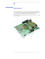
The following diagram shows where the different chips and connectors are
located on the system board.
Line Out
Line In
MIC
Battery
AGP Connector
Floppy
Connector
Secondary
IDE
Primary
IDE
Processor 1 Connector
Processor 2 Connector
Main
Power
Midi & Audio
Serial Port A
Serial Port B
(Both ports are stacked
with the Parallel Port)
Two USB
Mouse (upper) &
Keyboard (lower)
RIMM0
RIMM1
AUX
Power
CPU
Fan 1
Package Intrusion
CPU Fan 2
Main Fan
Memory
Controller Hub
(MCH)
SDRAM Memory Expansion Card Connector
PCI 1 Connector
Input/Output
Controller Hub (ICH)
PLL
Firmware
Hub (FWH)
MaxiLife
CD_IN
Status
Panel
Switches
(configuration
on page
40
)
PCI Fan
(MT only)
Spkr
Aux_IN
Wake-On
LAN (WOL)
SCSI LED
PCI 5 Connector
PCI 4 Connector
Audio Controller
PCI 3 Connector
PCI 2 Connector
Audio Codec
Super I/O
HDD
Thermal
Sensor (MT
only)

