


433
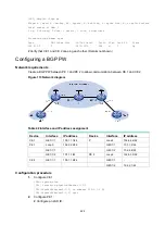
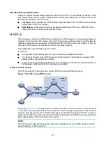
Figure 116 Network diagram
Table 45 Interface and IP address assignment
Device
Interface
IP address
Device
Interface
IP address
CE 1
GE1/1/1
100.1.1.1/24
ASBR 1
Loop0
192.2.2.2/32
PE 1
Loop0
192.1.1.1/32
GE1/1/2
23.1.1.2/24
GE1/1/2
23.1.1.1/24
GE1/1/1
26.2.2.2/24
PE 2
Loop0
192.4.4.4/32
ASBR 2
Loop0
192.3.3.3/32
GE1/1/2
22.2.2.1/24
GE1/1/1
26.2.2.3/24
CE 2
GE1/1/1
100.1.1.2/24
GE1/1/2
22.2.2.3/24
Configuration procedure
1.
Configure CE 1.
<CE1> system-view
[CE1] interface gigabitethernet 1/1/1
[CE1-GigabitEthernet1/1/1] ip address 100.1.1.1 24
[CE1-GigabitEthernet1/1/1] quit
2.
Configure PE 1:
# Configure an LSR ID.
<PE1> system-view
[PE1] interface loopback 0
[PE1-LoopBack0] ip address 192.1.1.1 32
[PE1-LoopBack0] quit
[PE1] mpls lsr-id 192.1.1.1
# Enable L2VPN.
[PE1] l2vpn enable
# Enable global LDP.
[PE1] mpls ldp
[PE1-ldp] quit
# Configure GigabitEthernet 1/1/2 (the interface connected to ASBR 1), and enable LDP on the
interface.
[PE1] interface gigabitethernet 1/1/2
[PE1-GigabitEthernet1/1/2] ip address 23.1.1.1 24
[PE1-GigabitEthernet1/1/2] mpls enable


