


296
224.0.0.0/4 Direct 0 0 0.0.0.0 NULL0
224.0.0.0/24 Direct 0 0 0.0.0.0 NULL0
255.255.255.255/32 Direct 0 0 127.0.0.1 InLoop0
5.
Verify that CE 3 and CE 4 can ping each other. (Details not shown.)
6.
Verify that CE 5 and CE 6 can ping each other. (Details not shown.)
7.
Verify that CE 3 and CE 6 cannot ping each other. (Details not shown.)
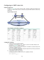
Configuring multirole host
Network requirements
Configure the multirole host feature to allow Host A to access VPN 1 and VPN 2 and Host B to
access only VPN 1.
Figure 80 Network diagram
Configuration procedure
1.
Configure CE 1:
# Configure IP addresses for interfaces.
<CE1> system-view
[CE1] interface gigabitethernet 1/1/1
[CE1-GigabitEthernet1/1/1] ip address 100.1.1.1 24
[CE1-GigabitEthernet1/1/1] quit
[CE1] interface serial 1/1/0
[CE1-Serial1/1/0] ip address 1.1.1.2 24
[CE1-Serial1/1/0] quit
# Configure a default route to PE 1.
[CE1] ip route-static 0.0.0.0 0 1.1.1.1
2.
Configure PE 1:
# Create VPN instances
vpn1
and
vpn2
for VPN 1 and VPN 2, respectively, and configure
different RDs and route targets for the VPN instances.
<PE1> system-view
[PE1] ip vpn-instance vpn1
[PE1-vpn-instance-vpn1] route-distinguisher 100:1
PE 1
PE 2
Ser1/1/0
2.1.1.1/24
Ser1/1/0
2.1.1.2/24
Ser1/1/1
3.1.1.2/24
Ser1/1/0
3.1.1.1/24
Ser1/1/1
1.1.1.1/24
Ser1/1/0
1.1.1.2/24
GE1/1/1
110.2.1.1/24
GE1/1/1
100.1.1.1/24
CE 1
CE 2
MPLS backbone
Host A
Host C
100.1.1.2/24
VPN 1
VPN 2
Host B
100.1.1.3/24
110.2.1.2/24


