


316
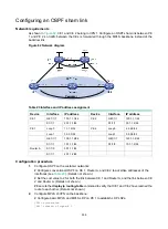
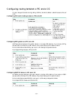
Figure 85 Network diagram
Table 26 Interface and IP address assignment
Device
Interface IP
address Device Interface IP
address
CE 1
Loop0
5.5.5.5/32
PE 1
Loop0
1.1.1.1/32
GE1/1/1 10.2.1.1/24
GE1/1/1 10.2.1.2/24
PE 2
Loop0
2.2.2.2/32
GE1/1/2 172.1.1.1/24
GE1/1/1 172.1.1.2/24
GE1/1/3 172.2.1.1/24
GE1/1/2 10.1.1.2/24 CE
2 Loop0
4.4.4.4/32
PE 3
Loop0
3.3.3.3/32 GE1/1/1
10.1.1.1/24
GE1/1/1 172.2.1.3/24
GE1/1/2 10.3.1.1/24
GE1/1/2 10.3.1.2/24
Configuration procedure
1.
Configure IP addresses and masks for interfaces as shown in
, and configure BGP and
MPLS L3VPN. (Details not shown.)
For more information about configuring basic MPLS L3VPN, see "
."
2.
Configure MPLS L3VPN FRR on PE 1:
# Configure BFD to test the connectivity of the LSP to 2.2.2.2/32.
<PE1> system-view
[PE1] mpls bfd enable
[PE1] mpls bfd 2.2.2.2 32
# Create routing policy
frr
, and specify the backup next hop as 3.3.3.3 for the route to
4.4.4.4/32.
[PE1] ip prefix-list abc index 10 permit 4.4.4.4 32
[PE1] route-policy frr permit node 10
[PE1-route-policy] if-match ip address prefix-list abc
[PE1-route-policy] apply fast-reroute backup-nexthop 3.3.3.3
[PE1-route-policy] quit
# Configure FRR for VPN instance
vpn1
to use routing policy
frr
.
[PE1] bgp 100
[PE1-bgp-default] ip vpn-instance vpn1
CE 2
CE 1
VPN 1
VPN 1
MPLS
backbone
PE 2
PE 1
PE 3
GE1/1/1
GE1/1/2
GE1/1/2
GE1/1/1
GE1/1/2
GE1/1/1
GE1/1/2
GE1/1/3
GE1/1/1
GE1/1/1
Loop0
Loop0
Loop0
Loop0
Loop0
Primary link
Backup link