


318
Configure MPLS L3VPN FRR on PE 2 to achieve the following purposes:
•
When the link PE 2—CE 2 operates correctly, traffic from CE 1 to CE 2 goes through the path
CE 1—PE 1—PE 2—CE 2.
•
When BFD detects that the link between PE 2 and CE 2 fails, traffic from CE 1 to CE 2 goes
through the path CE 1—PE 1—PE 2—PE 3—CE 2.
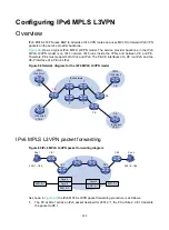
Figure 86 Network diagram
Table 27 Interface and IP address assignment
Device
Interface IP
address Device Interface IP
address
CE 1
Loop0
5.5.5.5/32
PE 2
Loop0
2.2.2.2/32
GE1/1/1 10.2.1.1/24
GE1/1/1 172.1.1.2/24
PE 1
Loop0
1.1.1.1/32 GE1/1/2
10.1.1.2/24
GE1/1/1 10.2.1.2/24
GE1/1/3 172.3.1.2/24
GE1/1/2 172.1.1.1/24 PE
3 Loop0
3.3.3.3/32
GE1/1/3 172.2.1.1/24
GE1/1/1 172.2.1.3/24
CE 2
Loop0
4.4.4.4/32 GE1/1/2
10.3.1.2/24
GE1/1/1 10.1.1.1/24
GE1/1/3 172.3.1.3/24
GE1/1/2 10.3.1.1/24
Configuration procedure
1.
Configure IP addresses and masks for interfaces as shown in
, and configure BGP and
MPLS L3VPN. (Details not shown.)
For more information about configuring basic MPLS L3VPN, see "
."
2.
Configure MPLS L3VPN FRR on PE 2:
# Configure the source IP address of BFD echo packets as 12.1.1.1.
<PE2> system-view
[PE2] bfd echo-source-ip 12.1.1.1
# Create routing policy
frr
, and specify the backup next hop as 3.3.3.3 for the route to
4.4.4.4/32.
[PE2] ip prefix-list abc index 10 permit 4.4.4.4 32
[PE2] route-policy frr permit node 10


