5–42
Maintenance and Service Guide
Removal and Replacement Procedures
5.17 Switch Cover
✎
Both switch cover spare part kits include the LED board and
LED board cable.
1. Prepare the computer for disassembly (
Section 5.3
).
2. Remove the keyboard (
Section 5.9
).
3. Turn the computer upside down with the rear panel
toward you.
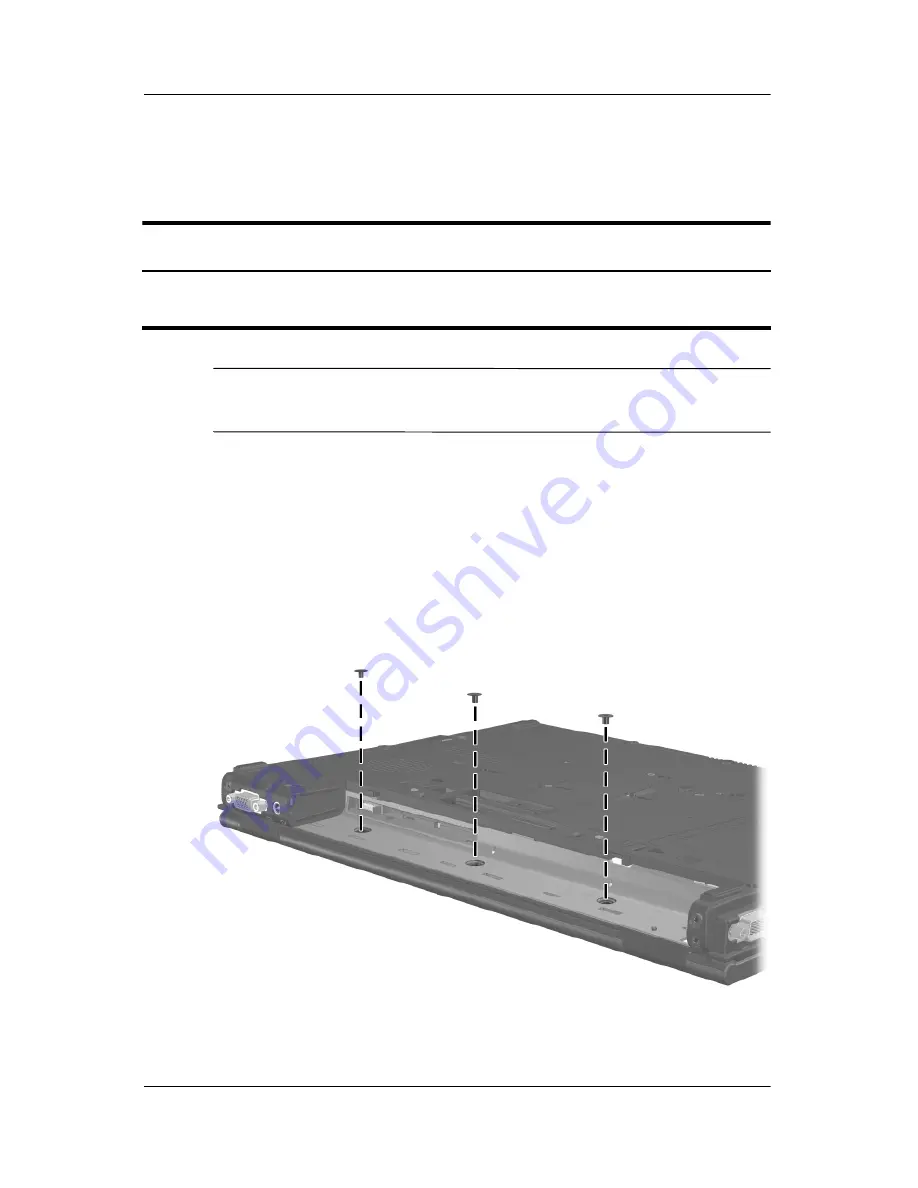
4. Remove the 3 Phillips PM2.0×2.0 screws that secure the
switch cover to the computer.
Removing the Switch Cover Screws
Switch Cover Spare Part Number Information
For use with nw8440 and nc8430 models
For use with nx8420 models
416405-001
416406-001
Summary of Contents for Compaq nw8440
Page 56: ...3 4 Maintenance and Service Guide Illustrated Parts Catalog Computer Major Components ...
Page 58: ...3 6 Maintenance and Service Guide Illustrated Parts Catalog Computer Major Components ...
Page 60: ...3 8 Maintenance and Service Guide Illustrated Parts Catalog Computer Major Components ...
Page 62: ...3 10 Maintenance and Service Guide Illustrated Parts Catalog Computer Major Components ...
Page 64: ...3 12 Maintenance and Service Guide Illustrated Parts Catalog Computer Major Components ...
Page 66: ...3 14 Maintenance and Service Guide Illustrated Parts Catalog Computer Major Components ...
Page 68: ...3 16 Maintenance and Service Guide Illustrated Parts Catalog 3 3 Plastics Kit ...
Page 70: ...3 18 Maintenance and Service Guide Illustrated Parts Catalog 3 4 Mass Storage Devices ...


