Chapter 4 System Support
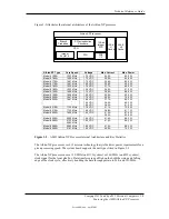
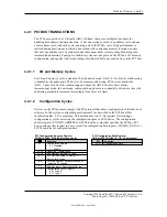
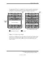
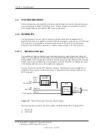
Two types of configuration cycles are used. A Type 0 (zero) cycle is targeted to a device on the
PCI bus on which the cycle is running. A Type 1 cycle is targeted to a device on a downstream
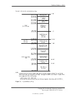
PCI bus as identified by bus number bits <23..16>. Figure 4-2 shows the configuration cycle
format and how the loading of 0CF8h results in a Type 0 configuration cycle on the PCI bus. The
Device Number (bits <15..11> determines which one of the AD31..11 lines is to be asserted high
for the IDSEL signal, which acts as a “chip select” function for the PCI device to be configured.
The function number (CF8h, bits <10..8>) is used to select a particular function within a PCI
component.
AD31..0
(w/Type 00
Config. Cycle)
NOTES:
[1] Bits <1,0> : 00 = Type 0 Cycle, 01 = Type 1 cycle
Type 01 cycle only. Reserved on Type 00 cycle.
Results in:
Register 0CF8h
Register
Index
Function
Number
IDSEL (only one signal line asserted)
23
16
Bus
Number
24
31
Function
Number
Register
Index
2
15 11
Device
Number
10
8
7
Reserved
1 0 [1]
Figure 4-2.
Configuration Cycle
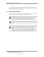
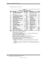
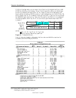
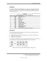
Table 4-1 shows the standard configuration of device numbers and IDSEL connections for
components and slots residing on a PCI bus.
Table 4-1.
PCI Device Configuration Access
Table 4-1.
PCI Component Configuration Access
PCI Component: Function
PCI
Bus #
Device #
Function #
Device ID [4]
IDSEL
Wired to: [4]
IGP:
CPU Host Bridge
Memory Configuration
Memory Addr. Trans. Cntrl.
Miscellaneous Control
AGP Host
Graphics processing unit [1]
0
0
0
0
0
1
0
0
0
0
30
0
0
1
2
3
0
0
01A4h / 01E0h
01Ach / 01EBh
01ADh / 01EEh
01AAh / 01EDh
01B7h / 01E8h
01A0h / 01F0h
n/a
AGP slot
1
0
0
[3]
n/a
MCP:
Legacy LPC Bridge Control
SMBus Control
USB Controller A
USB Controller B
USB 2.0 Controller
Network interface
Audio processor
Audio Codec
Modem Codec (not used)
PCI-PCI Bridge
IDE Controller
0
0
0
0
0
0
0
0
0
0
1
1
2
2
2
4
5
6
6
8
9
0
1
0
1
2
0
0
1
0
0
01B2h / 0060h
01B4h / 0064h
01C2h / 0067h
01C2h / 0067h
na / 0068h
[2] / 0066h
[2] / [2]
01B1h / 006Ah
01C1h / 0069h
01B8h / 006Ch
01BCh / 006Dh
n/a
PCI Connector 1 (slot 1)
2
6 / 4
[3]
[3]
AD22 / AD20
PCI Connector 2 (slot 2)
2
7 / 9
[3]
[3]
AD23 / AD25
PCI Connector 3 (slot 3)
2
8 / 10
[3]
[3]
AD24 / AD26
NOTES:
All numbers are in decimal unless otherwise indicated.
Vender ID for all functions is 10DEh.
[1] Will not be “visible” to software if an AGP card is installed in the AGP slot.
[2] Not used in this systems.
[3] Determined by installed device.
[4] D315 / d325
Compaq D315 and hp d325 Personal Computers
Featuring the AMD Athlon XP Processor
Second Edition – April 2003
4-4

