Technical Reference Guide
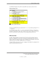
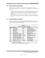
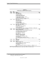
Table 4-13. System Operational Status LED Indication
Table 4-13.
System Operational Status LED Indications
System Status
D315
Power LED
d325
Power LED
S0: System on (normal operation)
Steady green
Steady green
S1: Suspend
Blinks green @ .5 Hz
Blinks green @ .5 Hz
S3: Suspend to RAM
Blinks green @ .5 Hz
Blinks green @ .5 Hz
S4: Suspend to disk
Off
Off
S5: Soft off
Off
Off
Processor not seated or installed
Steady red
Steady red
CPU thermal shutdown
See note [1]
See note [1]
No memory installed
Blinks red @ 2 Hz
Blinks red @ 2 Hz
Memory error
na
See note [2]
ROM flashing
See note [3]
See note [3]
Video error
na
See note [4]
PCA failure
na
See note [5]
Invalid ROM checksum error
na
See note [6]
System off
Off
Off
NOTE:
For both systems, HD LED is on (green) during hrd rive activity, off at all other times.
[1] Sequence; blinks red every second for 2 seconds, then off for two seconds.
[2] Sequence; blinks red five times in five seconds followed by two-second pause.
[3] Steady red when flashing ROM, then blinks green every second indicating user can restart.
[4] Sequence; blinks red six times in six seconds followed by two-second pause.
[5] Sequence; blinks red seven times in seven seconds followed by two-second pause.
[6] Sequence; blinks red eight times in eight seconds followed by two-second pause.
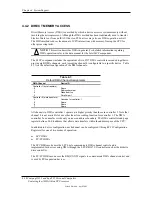
4.7.4 THERMAL SENSING AND COOLING
These systems feature variable-speed fans that are controlled through temperature sensing logic
on the system board and/or in the power supply. Typical cooling conditions include the
following:
1.
Normal – Low fan speed.
2.
Hot processor – ASIC directs Speed Control logic to increase speed of fan(s).
3.
Hot power supply – Power supply increases speed of fan(s).
4.
Sleep state – Fan(s) turned off. Hot processor or power supply will result in starting fan(s).
High and low thermal parameters are programmed into the ASIC by BIOS during POST. If the
high thermal parameter is reached then the fan(s) will be turned on full speed and the Therm-
signal will be asserted.
The system board provides connections for a heatsink-mounted CPU fan and a chassis fan, both
which complement the power supply fan. The system supports the use of variable-speed fans that
are regulated according to the temperature measured by an AMD1030 temperature controller.
Compaq D315 and hp d325 Personal Computers
Featuring the AMD Athlon XP Processor
Second Edition - April 2003
4-27

