background image

Component

Description

(4)

Volume mute button

Mutes and restores computer sound.

(5)

Volume down button

Decreases speaker sound.

(6)

Volume up button

Increases speaker sound.

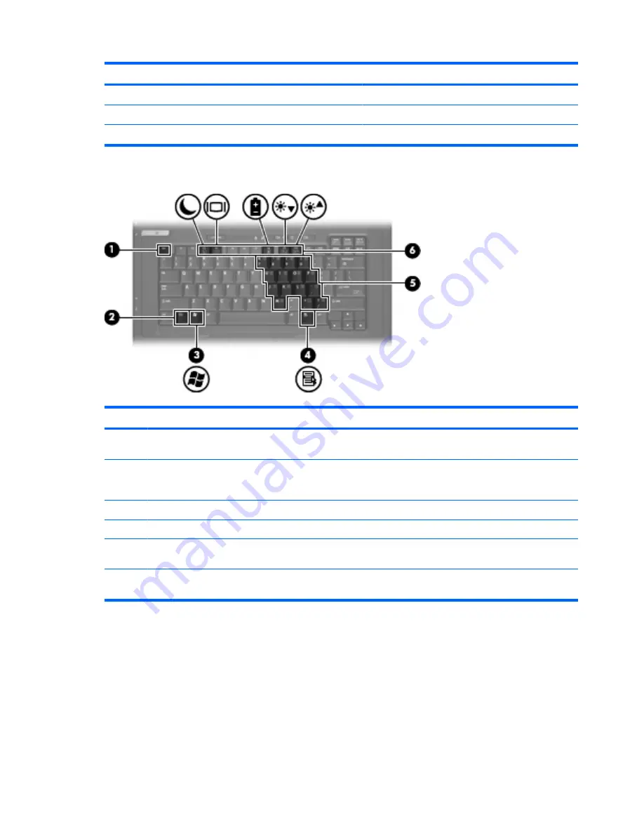
Keys

Component

Description

(1)

esc

 key

Displays system information when pressed in
combination with the 

fn

 key.

(2)

fn

 key

Executes frequently used system functions when
pressed in combination with a function key or the 

esc

key.

(3)

Windows logo key

Displays the Windows Start menu.

(4)

Windows applications key

Displays a shortcut menu for items beneath the pointer.

(5)

Embedded numeric keypad keys

Can be used like the keys on an external numeric
keypad.

(6)

Function keys

Execute frequently used system functions when pressed
in combination with the 

fn

 key.

4

Chapter 1   Notebook tour

Summary of Contents for Compaq 6720t

Page 1: ...HP Compaq 6720t Mobile Thin Client End User Reference Guide ...

Page 2: ...ce The only warranties for HP products and services are set forth in the express warranty statements accompanying such products and services Nothing herein should be construed as constituting an additional warranty HP shall not be liable for technical or editorial errors or omissions contained herein Second Edition March 2008 First Edition January 2008 Document Part Number 466204 002 ...

Page 3: ...llow another hard surface such as an adjoining optional printer or a soft surface such as pillows or rugs or clothing to block airflow Also do not allow the AC adapter to contact the skin or a soft surface such as pillows or rugs or clothing during operation The computer and the AC adapter comply with the user accessible surface temperature limits defined by the International Standard for Safety o...

Page 4: ...iv Safety warning notice ...

Page 5: ...Product notice This user guide describes features that are common to most models Some features may not be available on your computer v ...

Page 6: ...vi Product notice ...

Page 7: ...ing pointing device preferences 10 Connecting an external mouse 10 Using the keyboard 11 Using hotkeys 11 Displaying system information fn esc 11 Initiating Standby fn f3 12 Switching the screen image fn f4 12 Viewing battery charge information fn f8 12 Decreasing screen brightness fn f9 12 Increasing screen brightness fn f10 12 Using the keypads 13 Using the embedded numeric keypad 13 Enabling an...

Page 8: ...1 Storing a battery 22 Disposing of a used battery 22 Using external AC power 22 Connecting the AC adapter 23 5 Multimedia Using multimedia hardware 24 Using the audio features 24 Using the audio in microphone jack 25 Using the audio out headphone jack 25 Adjusting the volume 25 Using the video features 26 Using the external monitor port 26 Using multimedia software 26 Opening preinstalled multime...

Page 9: ...d 38 Requiring a power on password at restart 38 Installing a security cable 39 9 Connecting hardware Using a USB device 40 Connecting a USB device 40 Removing a USB device 41 Using the docking connector 41 Using PC Cards 41 Inserting and removing a PC Card 41 10 Hardware upgrades Identifying installed drives 44 Handling drives 44 Using optical drives select models only 45 Inserting an optical dis...

Page 10: ...x ...

Page 11: ...iption 1 TouchPad Moves the pointer and selects or activates items on the screen 2 Left TouchPad button Functions like the left button on an external mouse 3 TouchPad scroll zone Scrolls up or down 4 Right TouchPad button Functions like the right button on an external mouse This table describes factory settings To view or change pointing device preferences select Start Control Panel Printers and O...

Page 12: ...ck is on 4 Num lock light On Num lock is on 5 Volume mute light On Computer sound is turned off 6 Battery light Amber A battery is charging Blue A battery is close to full charge capacity Blinking amber A battery that is the only available power source has reached a low battery level When the battery reaches a critical battery level the battery light begins blinking rapidly Off If the computer is ...

Page 13: ... is visible whether the computer is open or closed Buttons and switches Component Description 1 Power button When the computer is off press the button to turn on the computer When the computer is in Standby press the button briefly to exit Standby If the computer has stopped responding and Windows shutdown procedures are ineffective press and hold the power button for at least 5 seconds to turn of...

Page 14: ... fn key 2 fn key Executes frequently used system functions when pressed in combination with a function key or the esc key 3 Windows logo key Displays the Windows Start menu 4 Windows applications key Displays a shortcut menu for items beneath the pointer 5 Embedded numeric keypad keys Can be used like the keys on an external numeric keypad 6 Function keys Execute frequently used system functions w...

Page 15: ...s headphones ear buds a headset or television audio 2 Audio in microphone jack Connects an optional computer headset microphone stereo array microphone or monaural microphone 3 USB ports 2 Connect optional USB devices 4 Optical drive select models only Reads an optical disc Left side components Component Description 1 Security cable slot Attaches an optional security cable to the computer Identify...

Page 16: ...dem jack Connects a modem cable 4 Vent Enables airflow to cool internal components 5 USB port Connects an optional USB device 6 PC Card slot Supports optional Type I and Type II 32 bit CardBus or 16 bit PC Cards Rear components Components Description 1 Power connector Connects an AC adapter 2 External monitor port Connects an external VGA monitor or projector Bottom components 6 Chapter 1 Notebook...

Page 17: ...nal components 8 Accessory battery connector Connects an optional accessory battery Wireless antennae Wireless antennae send and receive signals from one or more wireless devices These antennae are not visible from the outside of the computer NOTE For optimal transmission keep the areas immediately around the antennae free from obstructions To see wireless regulatory notices refer to the section o...

Page 18: ...label Provides regulatory information about the modem and lists the agency approval markings required by some of the countries in which the modem has been approved for use You may need this information when traveling internationally The modem approval label is affixed to the bottom of the computer Wireless certification label s Provide information about wireless devices and the approval markings o...

Page 19: ...protecting it from undesired flash memory writes In order to save changes to your system configuration settings you must commit your changes in the EWF Otherwise the new settings will be lost when the computer is shut down or restarted For additional information on the EWF see your network administrator Using the Enhanced Write Filter 9 ...

Page 20: ...ving it to the scroll zone Simply sliding your finger from the TouchPad to the scroll zone will not activate the scrolling function Setting pointing device preferences Use Mouse Properties in Windows to customize settings for pointing devices such as button configuration click speed and pointer options To access Mouse Properties select Start Control Panel Printers and Other Hardware Mouse Connecti...

Page 21: ...mage fn f4 Display battery information fn f8 Decrease screen brightness fn f9 Increase screen brightness fn f10 To use a hotkey command on the computer keyboard follow either of these steps Briefly press the fn key and then briefly press the second key of the hotkey command or Press and hold down the fn key briefly press the second key of the hotkey command and then release both keys at the same t...

Page 22: ...ted to the computer pressing fn f4 alternates the screen image from computer display to monitor display to simultaneous display on both the computer and the monitor Most external monitors receive video information from the computer using the external VGA video standard The fn f4 hotkey can also alternate images among other devices receiving video information from the computer The following video t...

Page 23: ...sed like the keys on an external numeric keypad Using the embedded numeric keypad The 15 keys of the embedded numeric keypad can be used like the keys on an external keypad When the embedded numeric keypad is enabled each key on the keypad performs the function indicated by the icon in the upper right corner of the key Enabling and disabling the embedded numeric keypad Press fn num lk to enable th...

Page 24: ...wercase Press and hold fn shift to type in uppercase Using an optional external numeric keypad Keys on most external numeric keypads function differently according to whether num lock is on or off num lock is turned off at the factory When num lock is on most keypad keys type numbers When num lock is off most keypad keys function like the arrow page up or page down keys When num lock on an externa...

Page 25: ...ay if the display is closed while the computer is on 2 Power lights 2 On The computer is on Blinking The computer is in Standby Off The computer is off 3 Power button When the computer is off press the button to turn on the computer When the computer is on press the button to turn off the computer When the computer is in Standby press the button briefly to exit Standby Power control and light loca...

Page 26: ...ry reaches a low battery level The 2 power lights display the same information The light on the power button is visible only when the computer is open The power light on the front of the computer is visible whether the computer is open or closed Shutting down the computer CAUTION Unsaved information will be lost when the computer is shut down The Shut Down command closes all open programs includin...

Page 27: ... Standby while reading from a disc or an external media card NOTE Hibernation is disabled at the factory NOTE You cannot initiate any type of networking connection or perform any computer functions while the computer is in Standby Initiating and exiting Standby NOTE Power settings and timeouts can be changed in Power Options With the computer on you can initiate Standby in any of the following way...

Page 28: ...charged battery is in the computer and the computer is not plugged into external power the computer runs on battery power When the computer is plugged into external AC power the computer runs on AC power If the computer contains a charged battery and is running on external AC power supplied through the AC adapter the computer switches to battery power if the AC adapter is disconnected from the com...

Page 29: ...laying When a battery is charging a lightning bolt icon may be superimposed over the battery icon on the Power Meter screen Inserting or removing the battery CAUTION Removing a battery that is the sole power source can cause loss of information To prevent loss of information shut down the computer through Windows before removing the battery To insert the battery 1 Turn the computer upside down on ...

Page 30: ...ys follow these recommendations If you are charging a new battery charge it fully before turning on the computer Charge the battery until the battery light turns off NOTE If the computer is on while the battery is charging the battery meter in the notification area may show 100 percent charge before the battery is fully charged Allow the battery to discharge below 5 percent of a full charge throug...

Page 31: ...power until the power lights turn off Resolving a low battery level when external power is available Connect one of the following devices AC adapter Optional docking device Optional power adapter Resolving a low battery level when a charged battery is available 1 Turn off the computer 2 Remove the discharged battery and then insert a charged battery 3 Turn on the computer Resolving a low battery l...

Page 32: ...ed Getting Started guide Using external AC power External AC power is supplied through one of the following devices WARNING To reduce potential safety issues use only the AC adapter provided with the computer a replacement AC adapter provided by HP or a compatible AC adapter purchased from HP Approved AC adapter Optional docking device Connect the computer to external AC power under any of the fol...

Page 33: ...ter If provided with a 3 pin attachment plug on the power cord plug the cord into a grounded earthed 3 pin outlet Do not disable the power cord grounding pin for example by attaching a 2 pin adapter The grounding pin is an important safety feature To connect the computer to external AC power follow these steps 1 Plug the AC adapter into the power connector 1 on the computer 2 Plug the power cord i...

Page 34: ...e mute button Mutes and restores computer sound 3 Volume down button Decreases computer sound 4 Volume up button Increases computer sound 5 Audio in microphone jack Connects an optional computer headset microphone stereo array microphone or monaural microphone 6 Audio out headphone jack Connects optional powered stereo speakers headphones ear buds a headset or television audio 24 Chapter 5 Multime...

Page 35: ... device such as external powered speakers or a stereo system When connecting a device to the headphone jack use only a 3 5 mm stereo plug When a device is connected to the headphone jack the speakers are disabled Adjusting the volume You can adjust the volume using the following controls Computer volume buttons Volume mute button Volume down button Volume up button Windows volume control a Click t...

Page 36: ... to the device Repeatedly pressing fn f4 alternates the screen image between the computer display the device and simultaneous display on both the computer display and the device Using multimedia software The computer includes preinstalled multimedia software Depending on the hardware and software included with the computer you can play digital media including audio and video CDs audio and video DV...

Page 37: ... DVD Do not connect or disconnect hardware while playing a disc Do not initiate Standby while playing a disc Otherwise you may see a warning message asking if you want to continue If this message is displayed click No After you click No the computer may behave in either of the following ways Playback may resume or The playback window in the multimedia program may close To return to playing the CD ...

Page 38: ... and two wireless lights All of the wireless devices on your computer are enabled at the factory so the wireless light is on blue when you turn on the computer The wireless light indicates the overall power state of your wireless devices not the status of individual devices If the wireless light is blue at least one wireless device is on If the wireless light is off all wireless devices are off Be...

Page 39: ...standard supports data rates of up to 11 Mbps and operates at a frequency of 2 4 GHz 802 11g supports data rates of up to 54 Mbps and operates at a frequency of 2 4 GHz An 802 11g WLAN device is backward compatible with 802 11b devices so they can operate on the same network 802 11a supports data rates of up to 54 Mbps and operates at a frequency of 5 GHz Setting up a WLAN To set up a WLAN and con...

Page 40: ... Check with each public WLAN location for cost and connection requirements Using wireless security features When you set up a WLAN or access an existing WLAN always enable security features to protect your network from unauthorized access The most common security levels are Wi Fi Protected Access WPA Personal and Wired Equivalent Privacy WEP When setting up a network use one or more of the followi...

Page 41: ...ital line can permanently damage the modem Immediately disconnect the modem cable if you accidentally connect it to a digital line If the modem cable contains noise suppression circuitry 1 which prevents interference from TV and radio reception orient the circuitry end 2 of the cable toward the computer Connecting a modem cable WARNING To reduce the risk of electric shock fire or damage to the equ...

Page 42: ...sed the computer you must obtain a country specific modem cable adapter To connect the modem to an analog telephone line that does not have an RJ 11 telephone jack follow these steps 1 Plug the modem cable into the modem jack 1 on the computer 2 Plug the modem cable into the country specific modem cable adapter 2 3 Plug the country specific modem cable adapter 3 into the telephone wall jack 32 Cha...

Page 43: ...r pulse or tone dialing An analog telephone line supports one of 2 dialing modes pulse dialing or tone dialing These dialing mode options are selected in the Phone and Modem Options settings The dialing mode option selected must match the dialing mode supported by the telephone line in your location To determine the dialing mode supported by a telephone line dial a few digits on the telephone and ...

Page 44: ... 4 Click Properties 5 Click Modem 6 Clear the check box for Wait for dial tone before dialing 7 Click OK twice NOTE You must commit these changes in order for them to be saved See your network administrator for additional information Connecting to a local area network Connecting to a local area network LAN requires an 8 pin RJ 45 network cable purchased separately If the network cable contains noi...

Page 45: ... of the cable into a network wall jack 2 WARNING To reduce the risk of electric shock fire or damage to the equipment do not plug a modem or telephone cable into the RJ 45 network jack Connecting to a local area network 35 ...

Page 46: ... referred to hearafter as Computer Setup NOTE Computer Setup is a non Windows utility accessed by pressing f10 when the computer is turned on or restarted When using Computer Setup you must use the keys on your computer to navigate and make selections To protect against Use this security feature Unauthorized use of the computer Power on authentication using passwords Administrator passwords User p...

Page 47: ...e the following tips for creating and saving passwords When creating passwords follow requirements set by the program Write down your passwords and store them in a secure place away from the computer Do not store passwords in a file on the computer The following tables list commonly used passwords and describe their functions Setting passwords in Windows Windows passwords Function Administrator pa...

Page 48: ...nces go into effect when the computer restarts Entering a power on password At the Power on Password prompt type your password using the same kind of keys you used to set the password and then press enter After 3 unsuccessful attempts to enter the password you must turn off the computer turn it back on and then try again Requiring a power on password at restart In addition to requiring that a powe...

Page 49: ...ed or stolen 1 Loop the security cable around a secured object 2 Insert the key 1 into the cable lock 2 3 Insert the cable lock into the security cable slot on the computer 3 and then lock the cable lock with the key NOTE Your computer may look different from the illustration The location of the security cable slot varies by model Installing a security cable 39 ...

Page 50: ...tandard USB ports Depending on your computer model the USB port on the left side of the computer is either a standard USB port or a powered USB port A powered USB port provides power to an external device if it is used with a powered USB cable The USB ports on the computer support USB 1 0 USB 1 1 and USB 2 0 devices An optional docking device or USB hub provides additional USB ports that can be us...

Page 51: ...anced Docking Station is not supported on this computer Using PC Cards NOTE For information regarding the status of the PC Card slot contact your network administrator Inserting and removing a PC Card CAUTION To prevent damage to the computer and external media cards do not insert an ExpressCard into a PC Card slot CAUTION To prevent damage to the connectors Use minimal force when inserting a PC C...

Page 52: ...o release the insert 3 Pull the insert out of the slot 2 To insert a PC Card follow these steps 1 Hold the card label side up with the connectors facing the computer 2 Insert the card into the PC Card slot and then push in on the card until it is firmly seated NOTE An inserted PC Card uses power even when idle To conserve power stop or remove a PC Card when it is not in use 42 Chapter 9 Connecting...

Page 53: ...To stop a data transfer click Cancel in the operating system Copying window 2 Release and remove the PC Card a Press the PC Card eject button 1 This action extends the button into position for releasing the PC Card b Press the PC Card eject button again to release the PC Card c Pull the PC Card 2 out of the slot Using PC Cards 43 ...

Page 54: ...o clear Before handling a drive discharge static electricity by touching the unpainted metal surface of the drive Do not touch the connector pins on a removable drive or on the computer Handle a drive carefully do not drop a drive or place items on it When the battery is the only source of power be sure that the battery is sufficiently charged before writing to media Avoid exposing a drive to temp...

Page 55: ... RW discs Write to DVD RW discs Write to DVD R DL discs DVD ROM Yes No No No CAUTION To prevent possible audio and video degradation or loss of audio or video playback functionality do not initiate Standby while reading from a CD or DVD If Standby is initiated during playback of a disc you may experience the following behaviors Your playback may be interrupted You may see a warning message asking ...

Page 56: ...ouching the flat surfaces and position the disc label side up over the tray spindle NOTE If the tray is not fully accessible tilt the disc carefully to position it over the spindle 5 Gently press the disc 3 down onto the tray spindle until the disc snaps into place 6 Close the disc tray NOTE After you insert a disc a short pause is normal before playback begins 46 Chapter 10 Hardware upgrades ...

Page 57: ...tray and then gently pull out the tray 2 until it stops 2 Remove the disc 3 from the tray by gently pressing down on the spindle while lifting the outer edges of the disc Hold the disc by the edges and avoid touching the flat surfaces NOTE If the tray is not fully accessible tilt the disc carefully as you remove it 3 Close the disc tray and place the disc in a protective case Using optical drives ...

Page 58: ...hen pull out the tray 2 until it stops 3 Remove the disc 3 from the tray by gently pressing down on the spindle while lifting the outer edges of the disc Hold the disc by the edges and avoid touching the flat surfaces NOTE If the tray is not fully accessible tilt the disc carefully as you remove it 4 Close the disc tray and place the disc in a protective case 48 Chapter 10 Hardware upgrades ...

Page 59: ... can of compressed air with a straw extension can be used to blow air around and under the keys to loosen and remove debris Traveling and shipping The computer is built to go with you For best results follow the traveling and shipping tips described here To prepare the computer for traveling and shipping follow these steps 1 Back up your information 2 Be sure that the optical drive and PC Card slo...

Page 60: ... an 802 11b g a Global System for Mobile Communications GSM or a General Packet Radio Service GPRS device note that the use of these devices may be restricted in some environments Such restrictions may apply onboard aircraft in hospitals near explosives in hazardous locations and so on If you are uncertain of the policy that applies to the use of a particular device ask for authorization to use it...

Page 61: ...g the display 49 cleaning the keyboard 49 compartments memory module 7 components bottom 6 front 5 left side 5 right side 5 wireless antennae 7 Computer Setup power on password 37 connecting to a WLAN 30 connection external power 23 connectors accessory battery 7 docking 7 conservation power 21 copyright warning 27 cord power 50 corporate WLAN connection 30 country specific modem cable adapter 32 ...

Page 62: ...g adding location 33 travel connection problems 33 monitor connecting 26 mouse external connecting 10 setting preferences 10 multimedia software opening 26 using 27 mute button 24 25 N network cable connecting 34 noise suppression circuitry 34 network jack identifying 6 noise suppression circuitry modem cable 31 network cable 34 num lock light identifying 2 num lock external keypad 14 O operating ...

Page 63: ...off the computer 16 U unresponsive system 16 USB cable connecting 40 USB devices connecting 40 description 40 removing 41 USB hubs 40 USB ports identifying 5 6 40 user password 37 V vents identifying 6 7 video transmission types 12 volume down button 4 24 volume mute button 4 24 25 volume mute light identifying 2 volume up button 4 24 volume adjusting 25 W Windows applications key identifying 4 Wi...

Page 64: ......

Reviews: