


frequency
range
(start
and
stop
frequency)
are
c
hanged.
Therefore,
y
ou
may
ha
v
e
an
uncalibrated
state
while
the
CAL
SEQ
light
is
on.
Be
sure
the
receiv
er
is
calibrated
for
the
curr
ent
instrumen
t
settings.
12.
Disconnect
the
preselector
section's
com
b
generator
output
and
reconnect
the
signal
source
to
receiv
er
INPUT
1 .
Use
the
same
cable
during
measuremen
ts
that
y
ou
used
for
calibration;
the
system
has
comp ensated
for
the
loss
in
this
cable.
Remem
b er
to
accoun
t
for
the
losses
in
the
calibration
cable
if
y
ou
do
not
use
that
same
during
the
actual
measuremen
t.
Using
other
cables
may
in
tro duce
an
amplitude
error.
13.
Press
4
MAX
HOLD
5
on
the
sp ectrum
analyzer.
Allow
the
display
to
ll
in.
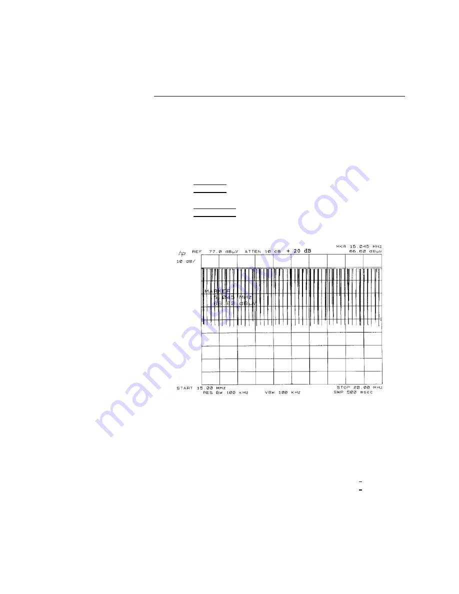
14.
Press
4
PEAK
SEARCH
5
on
the
sp ectrum
analyzer
and
read
the
marker
amplitude
on
the
display
.
Refer
to
Figure
4-10.
Figure
4-10.
P
eak
Measurement
of
a
Broadband
Signal
Example:
Micro
w
a
v
e
P
eak
Measuremen
t
(CW
Signal)
This
example
makes
p eak
or
a
v
erage
measuremen
ts
on
a
microw
a
v
e
signal
in
the
2
GHz
to
22
GHz
range.
1.
Connect
the
100
MHz
calibration
signal
from
the
sp ectrum
analyzer
to
receiv
er
INPUT
2 .
Select
receiv
er
INPUT
2
.
2.
Select
the
preamplier
BYP
ASS
path
b
y
pressing
0
4
5
on
the
switch
driv
er.
The
LED
in
the
k
ey
will
light.
3.
Select
the
RF
preselector
BYP
ASS
path
b
y
pressing
the
ENABLE
k
ey
and
the
BYP
ASS
k
ey
.
4-14
Making
Typical
Measurements
HP
8572A
EMI
Receiv
er
User's
Guide


