6-28
Removal and Replacement
ENCODER STRIP REMOVAL
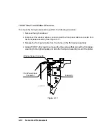
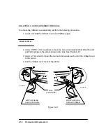
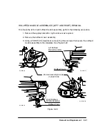
To remove the encoder strip, refer to Figure 6-20 and perform the following steps:
1. Remove the window assembly.
2. Remove the left and right endcovers.
W A R N I N G
3. Using a 5.5 mm nut driver, remove the nut and washer that secure the encoder strip to
the right side encoder spring-bracket. See Figure 6-20.
4. Using a 5.5 mm nut driver, remove the nut and washer that secure the ground strap
and encoder strip to the service station.
5. Compress the encoder spring-bracket to release tension on the encoder strip.
6. Carefully release the encoder strip from the encoder spring-bracket.
7. Carefully pull the encoder strip through and out of the carriage assembly.
When installing the encoder strip, do the following:
1. Ensure that the encoder strip is oriented with the transparent area down. Thread the
strip through the apertures in the pen carriage assembly.
2. Using a 5.5 mm nut driver, install the ground strap, washer and nut that secure the
encoder strip to the service station. Make sure the encoder strip engages the two
small tabs adjacent to the threaded post on the service station.
3. Press the forward end of the encoder spring-bracket slightly inward and place the
encoder strip between the tabs of the encoder spring-bracket and over the threaded
post on the encoder spring-bracket.
4. Using a 5.5 mm nut driver, install the washer and nut that secure the encoder strip to
the encoder spring-bracket.
5. Slide the carriage back and forth the length of its travel to ensure free movement. The
encoder strip should not bind or rub on the carriage. To adjust the encoder strip, loos-
en the spring-bracket screws and move the bracket up or down as necessary. Center
the encoder strip in the pen carriage apertures and tighten the spring-bracket screws.
Summary of Contents for 650c - DesignJet Color Inkjet Printer
Page 1: ...PrinterFAQ COM HP DesignJet650C User Guide ...
Page 126: ...7 10 Adjustments Calibrations Notes ...
Page 156: ...9 4 Product History Notes ...
Page 165: ...10 9 Parts and Diagrams Illustrated Parts Breakdown C2859A Electronics Enclosure C C2858 3 1 ...
Page 167: ...10 11 Parts and Diagrams Illustrated Parts Breakdown C2858A Electronics Enclosure C C2858 4 1 ...
Page 183: ...10 27 Parts and Diagrams Illustrated Parts Breakdown Paper Drive Assemblies C C2858 12 1 ...
Page 199: ......


