background image

3-5

Installation and Configuration

Real-time switching between plotting modes is not supported. If the user selects another
mode while plotting, the plotter waits until the current plot is finished and then switches to the
newly selected mode.

MEDIA CUTTING AND STACKING

Automatic and manual cutting of plots is available on the C2858/9A. In roll media opera-
tions, the user can choose between continuous plotting or cutting plots off the roll automati-
cally as they are completed.

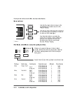
Automatic cutting

When roll media is loaded, whether or not queueing is 

ON, the plotter automatically cuts plots and drops them 
into the media bin. When queueing and nesting are ON, 
the plotter cuts each nest. The automatic cutter can be 
programmatically disabled. When cutting is disabled, the
plotter draws tick marks at the plot margins to indicate 
the end of a plot or nest. The automatic cutter can be 
enabled programmatically or by cycling power.

Manual cutting

The front panel 

Form Feed/Cut

 button can be used to 

feed the media out and cut it after a plot is completed.

Media stacking

Unattended stacking of cut sheets is provided by the 

adjustable media bin. The user must adjust the movable 
shelf of the bin according to the length of the cut sheets. 
Bin capacity is 20 sheets.

Manual cutter

A manual cutter is provided with the plotter for hand-

cutting of media and is stored in the manual holder on 
the back of the plotter.

Summary of Contents for 650c - DesignJet Color Inkjet Printer

Page 1: ...PrinterFAQ COM HP DesignJet650C User Guide ...

Page 2: ...es directly to HP C2858A and C2859A plotters with serial numbers prefixed USA For additional information about serial numbers see SERIAL NUMBER INFORMATION in Chapter 1 HEWLETT PACKARD COMPANY 1993 16399 W BERNARDO DRIVE SAN DIEGO CALIFORNIA 92127 1899 C2858 90000 Printed March 1993 ...

Page 3: ...djustments Calibrations Chapter8 Troubleshooting Chapter9 Product History Chapter10 Parts and Diagrams Chapter 1 Product Information This chapter contains general information regarding the C2858A and C2859A DesignJet 650C plotters A description of the plotters features options and accessories performance characteristics and serial number information is included in this chapter Chapter 2 Site Plann...

Page 4: ...d to return the plotter to proper operating condition Chapter 8 Troubleshooting Included in Chapter 8 are service tests error codes and messages and diagnostic information to assist you in troubleshooting and solving plotter symptoms and failures Chapter 9 Product History Chapter 9 provides historical tracking of changes made to the plotters The differences between earlier versions of the plotters...

Page 5: ...ations 2 2 Power Requirements 2 2 Line Cord Set 2 2 Environmental Specifications 2 3 Physical Specifications 2 3 Cable Restrictions 2 4 RS 232 C Interface 2 4 Centronics Interface 2 4 HP IB Interface 2 4 3 Installation and Configuration Introduction 3 1 Installation Instructions 3 2 User Installable Modules 3 2 Connectivity 3 2 Line Voltage and Fusing 3 2 Power Cord Configurations 3 2 User Informa...

Page 6: ... 3 21 Front Panel Messages 3 22 Operational Verification 3 26 Power On Self Test 3 26 Demonstration Plot 3 26 4 Preventive Maintenance Introduction 4 1 Effect on Product Reliability 4 2 Preventive Maintenance Procedures 4 2 General Cleaning 4 2 Drive Roller Cleaning 4 3 5 Functional Overview Introduction 5 1 Simplified Description of Circuits 5 2 Mechanical Overview 5 3 Printed Circuit Assembly PC...

Page 7: ...mbly and Sensor Removal 6 17 Pinch Wheel Sensor Removal 6 18 Window Sensor Removal 6 19 Media Sensor Removal 6 20 Trailing Cable Removal 6 21 Back Panel Removal 6 23 Front Panel Removal 6 24 Carriage Motor Removal 6 25 Paper Motor Removal 6 26 Encoder Strip Removal 6 28 Rollfeed Cover Assembly Removal 6 30 Rollfeed Module Assemblies Left and Right Removal 6 31 Cutter Assembly Removal 6 32 Trailing...

Page 8: ...on 7 4 Media Sensor Calibration 7 6 Drop Detect Calibration 7 7 Edge Sensor Calibration 7 8 Bail Calibration 7 9 8 Troubleshooting Introduction 8 1 Diagnostics 8 2 Power On Self Tests 8 2 Power On Self Test 8 2 Mechanical Initialization 8 3 Error Messages and Codes 8 4 Worded Error Messages 8 4 System Error Codes 8 7 Display Data Plot 8 11 Servo System Control Failures 8 11 Troubleshooting Tips 8 ...

Page 9: ...ction 9 1 History of Assemblies by Serial Number 9 2 History of Printed Circuit Assemblies PCAs 9 3 10 Parts and Diagrams Introduction 10 1 Exchange Assemblies 10 2 Replaceable Parts 10 2 Illustrated Parts Breakdown Drawings 10 2 Labels and Cables 10 2 ...

Page 10: ...Used for a signal common as well as providing protection against electrical shock in case of a fault A terminal marked with this symbol must be connected to ground in the manner described in the installation operating manual and before operating the equipment Frame or chassis terminal A connection to the frame chassis of the equipment which normally includes all exposed metal Alternating current D...

Page 11: ...s Also provided are descriptions of the plotters information on the plotter features options and accessories performance characteristics and plotter serial number information Introduction 1 1 Description 1 2 Options 1 4 Plug in Memory 1 4 ROM Enhancement Modules 1 4 Modular Input Output MIO PCAs 1 4 Accessories 1 5 Performance Characteristics 1 6 Serial Number Information 1 6 ...

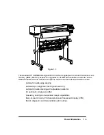
Page 12: ... special inkjet compat ible drafting film Quality color output is only supported when using HP special inkjet paper C2858 9A DesignJet 650C plotters can produce plots on single sheet media or roll feed me dia Large format plots of high resolution and quality are generated for applications such as computer aided design CAD computer aided manufacturing CAM mapping mechani cal and architectural drawi...

Page 13: ... enhancement and modular I O options Other features that are standard include Automatic media edge sensing Automatic pen alignment testing and servicing Automatic media stacking with adjustable media bin An automatic single axis cutter Queueing nesting and expanded margin capabilities Easy to read 2 row by 20 character vacuum fluorescent display VFD Built in diagnostic and demonstration plot routi...

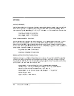
Page 14: ...ap anese users who require the Kanji character sets A PostScript upgrade is also available in ROM SIMM The part numbers for the kits are Kanji ROM Kit P N C2847 60031 PostScript ROM Kit P N C2882A MODULAR INPUT OUTPUT MIO PCAs Interface circuitry is provided on the plotters which allows the user to install HP supported modular I O MIO cards for several interface applications Although multiple prot...

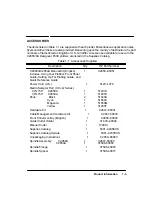
Page 15: ...des Using Your Plotter s Front Panel Guide Setting Up For Plotting Guide and Quick Reference Guide 1 C2858 90051 Power Cord U S 1 8120 1378 Media Sampler Roll CX Jet Series 24ºx150 C2858A 36ºx150 C2859A 1 1 51631D 51631E Pens Black Cyan Magenta Yellow 2 1 1 1 51640A 51650C 51650M 51650Y Hardware Kit 1 C2847 60061 Cable Management Hardware Kit 1 C2847 60030 Front Panel Overlay English 1 C2858 60026...

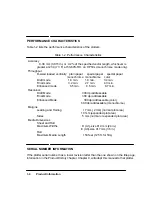
Page 16: ... 3 min Enhanced mode 6 5 min 6 5 min 8 7 min Resolution Draft Mode 300 dpi addressable Final Mode 300 dpi addressable Enhanced Mode 300 dpi addressable color 600 dpi addressable monochrome Margins Leading and Trailing 17 mm 2mm normal plot area 10 mm expanded plot area Sides 5 mm normal or expanded plot area Media Dimensions Sheet and Roll Maximum Widths D A1 size 619 mm 24 in E A0 size 917 mm 36 ...

Page 17: ... of HP C2858Aand C2859Aplotters Also included is information on environmental operat ing conditions and physical specifications for the plotters Introduction 2 1 Electrical Specifications 2 2 Power Requirements 2 2 Line Cord Set 2 2 Environmental Specifications 2 3 Physical Specifications 2 3 Cable Restrictions 2 4 RS 232 C Interface 2 4 Centronics Interface 2 4 HP IB Interface 2 4 ...

Page 18: ... ments for the plotters Table 2 1 Power Requirements Voltage Requirements Frequency Source Voltage Current max 100 Vac 1 4 A 120 Vac 1 2 A 220 Vac 650 mA 240 Vac 600 mA 47 53 Hz and 57 63 Hz Consumption 140 Watts maximum LINE CORD SET W A R N I N G The configuration of the ac line cord set required for use with the plotters is determined by the country of destination for the plotters Refer to Chap...

Page 19: ...S The plotter physical specifications are listed in Table 2 3 Table 2 3 Physical Specifications Length Depth Height Weight Packaging Plotter Body Length Width Height Weight Leg Pack Length Width Height Weight C2858A C2859A 1092 mm 43 in 1372 mm 54 in 711 mm 28 in 711 mm 28 in 1169 mm 46 in 1219 mm 48 in 58 kg 128 lbs 70 kg 155 lbs 1270 mm 50 in 1574 mm 62 in 584 mm 23 in 584 mm 23 in 635 mm 25 in ...

Page 20: ...ded for the RS 232 C Interface Longer cables are permissible provided the load capacitance does not exceed 2500 picofarads CENTRONICS INTERFACE The use of short cables each less than 2 metres or 6 6 feet is recommended for the Centron ics Interface HP IB INTERFACE The HP IB Hewlett Packard Interface Bus allows up to 15 devices to be connected The maximum cable length is restricted to 2 metres 6 6 ...

Page 21: ...3 2 Line Voltage and Fusing 3 2 Power Cord Configurations 3 2 User Information and Operation 3 4 Media Guidelines 3 4 Media Type and Print Quality 3 4 Media Cutting and Stacking 3 5 Usable Media Sizes 3 6 Loading Roll Media 3 6 Unloading Roll Media 3 10 Loading Sheet Media 3 11 Unloading Sheet Media 3 12 Clearing Media Jams 3 12 Pen Checking 3 13 Accessing Pens 3 14 Replacing Pens 3 14 Selectable ...

Page 22: ... cards can be easily changed to match the de sired application Installation instructions are provided with the modules and also provided in Chapter 6 of this manual Information on ordering the modular I Os is provided in Chapter 1 of this manual CONNECTIVITY Depending upon the interface and hardware being used to drive the plotters different cables could be required A listing of cables and other c...

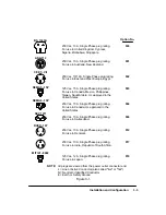
Page 23: ...abwe Singapore 250 Vac 10 16 A Single Phase plug rating For use in East and West Europe Egypt 125 Vac 15 A Single Phase plug rating For use in Canada Mexico Philippines Taiwan Saudi Arabia UL approved in the United States 250 Vac 10 A Single Phase plug rating For use in Switzerland 250 Vac 10 A Single Phase plug rating For use in Denmark 250 Vac 10 A Single Phase plug rating For use in India Repub...

Page 24: ...ons of plotting modes Each mode is depen dent upon the color monochrome setting media type and print quality settings input through the front panel Interaction between the settings produces the ten modes Each mode has a unique combination of print resolution number of passes and resultant ink drying time Media Type is set through the front panel when media is loaded into the plotter The front pane...

Page 25: ...them into the media bin When queueing and nesting are ON the plotter cuts each nest The automatic cutter can be programmatically disabled When cutting is disabled the plotter draws tick marks at the plot margins to indicate the end of a plot or nest The automatic cutter can be enabled programmatically or by cycling power Manual cutting The front panel Form Feed Cutbutton can be used to feed the me...

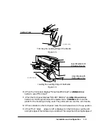
Page 26: ...dia into the plotter put a roll of media on the plotter spindle and insert the spindle in the plotter by performing the following steps W A R N I N G Be sure that the plotter wheels are locked to prevent the plotter from moving while loading roll media To lock the wheels press the locking levers on the wheels to the down position 1 Standing the spindle on the end opposite the large scalloped media...

Page 27: ...3 7 Installation and Configuration Figure 3 2 Removing the Media Stop and Endcap C C2847 10 UM Figure 3 3 Sliding the New Roll onto the Spindle C C2847 16 UM ...

Page 28: ... edge of the media If it appears uneven or to ensure a straight edge the edge will need to be trimmed W A R N I N G The cutter blade is very sharp Use caution when using the cutter to trim or cut media Keep hands away from the blade when cutting Retract the blade into the cutter after use 8 Trim the leading edge if it s uneven Pull it over the top of the plotter and lay it over the cutting track U...

Page 29: ...button to select ªRoll load º 11 When the front panel displays ªSELECT MEDIA º press the Up orDown Arrow button to scroll through and select the media choice Press the Enter button to set the plotter for the media type being used The plotter will now load the roll of media 12 When indicated on the front panel raise the pinchwheel lever to the up position 13 When ªPull Align edges to rollº is displ...

Page 30: ... outside the roll cov er then close the roll cover Press the Down Arrowbutton to continue The plotter trims off the first few inches of media When roll loading is complete the ªSTATUS Ready to plotº message is displayed UNLOADING ROLL MEDIA To unload roll media from the platen without removing the spindle from the plotter do the following steps 1 Raise the pinchwheel lever to the up position 2 Ope...

Page 31: ...y as it hits the stops inside the plotter The buckling should be even across the width of the sheet Let go as soon as the plotter begins to pull the media in 4 When the front panel displays ªSheet load Roll load º press the Up Arrowbutton to select ªSheet load º 5 When the front panel displays ªSELECT MEDIA º press the Up orDown Arrow button to scroll through and select the media choice Press the ...

Page 32: ... press the Form Feed Cut button and remove the sheet when the plotter is finished feeding it out Another way to remove unplotted sheet media is to raise the pinchwheel lever at the right remove the sheet and lower the lever CLEARING MEDIA JAMS To clear a media jam first press the Form Feed Cut button to see if the plotter will cut and advance the media out Should the jam remain turn the plotter OF...

Page 33: ...eplaced nozzles aren t working or reseated poor electrical contact The defective pen position is indicated by a flashing icon in the front panel display When Pen checking is OFF the plotter does not check the pens for the above problems the only way you ll be able to tell if you need to replace or reseat a pen is if your print quality is poor Use the ink level indicators on the cartridges to check...

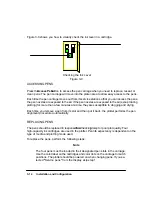
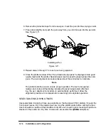
Page 34: ...few minutes at a time they are susceptible to clogging and drying Each time you remove a pen from its slot and then put it back the plotter performs the pen alignment procedure automatically REPLACING PENS The pens should be replaced in response to a Pen Checking prompt or poor plot quality Four high capacity ink cartridges are used in the plotter Pen life expectancy is dependent on the type of me...

Page 35: ...to the pen service station 3 Refer to the plotter display The display indicates via flashing icon s which pen position s is are detected to be in need of servicing The four icons represent the following pen positions outer left Y yellow inner left M magenta inner right C cyan outer right K black Note In monochrome mode only the black pen icon will appear solid while the remaining icons are outline...

Page 36: ...out three minutes to complete Note The plotter tests the pens to ensure proper operation The test runs approxi mately one minute and the display indicates the pens being tested After test ing the pen alignment procedure is automatically performed Allow the alignment procedure to complete before resuming normal plotter operation SELECTABLE INK DRYING TIMES User selectable ink drying times are avail...

Page 37: ... available through 3 pen media action buttons LEDs associated with various buttons are used to indi cate whether the function is enabled or disabled The front panel is shown in Figure 3 12 Cancel Form Feed Cut Access Pens Enhanced Final Draft Previous Busy Enter menu buttons plot mode buttons message display action buttons Pause Color Mono L C2858 1 The front panel display is used for plotter set ...

Page 38: ...Mono and print quality buttons Color Mono Plotter set to plot in Enhanced Final or Draft modes LED will be lit for mode selected Sets the resolution quality parameter for the media type being used Enhanced Final Draft Select Color mode or Mono black and white mode Plot Type Media Type Print Quality Resolution dpi Passes Pass Density Mono Paper Draft Final Enhanced 300 addressable 300 addressable 6...

Page 39: ... you want is displayed press the Enter button 4 Repeat from step 2 to reach the next level or sublevel of options you want to set Note Many menus contain subgroups of plotter options Pressing Enterthen dis plays the next level of options When you have reached the final level of your option pressing Enterconfirms your menu selection or value In many instances your choice is saved in the plotter s c...

Page 40: ...setup including graphics language dry time pen checking and media bypass conditions I O Setup Controls plotter I O configuration and interaction with the controller For configuring the RS 232 and MIO interfaces and parameters Two user customized RS 232 configurations can be stored in memory Demo Plot Accesses the internal demonstration plot routine Utilities Accesses accuracy calibration procedure...

Page 41: ...uese ªPortugueseº and Japanese Katakana characters To change the display language or if the display is in a language you cannot understand use the following procedure to get to a language you do understand 1 Turn the plotter OFF 2 Press and hold down the Enter button while turning the plotter ON Release the Enter button 3 Using the arrow buttons scroll to the desired language to be displayed and p...

Page 42: ...sented in Chapter 8 of this manual Table 3 2 State Messages Message State Accessing pens You have pressed the Access Pens button The pen carriage is moving out so you can access it Aligning pens Machine is aligning pens Cancelling You have pressed the Cancel button and the plotter is in the process of cancelling the procedure You may continue when this message is no longer displayed Checking media...

Page 43: ... config saved The baud handshake and parity settings you just entered for your RS 232 C configuration have been saved as either Config A or Config B whichever you specified STATUS Initializing Machine is doing internal checking upon power up STATUS Out of media The plotter has detected that the roll is empty you must be in Roll mode for this to happen If desired remove the old roll and insert a ne...

Page 44: ... Load arrow edge print side down Remove accuracy calibration plot turn it so that the edge with arrows printed on it is print side down then load that edge into the plotter Load cancelled Remove media You pressed the Cancel button while media loading was in progress Remove media Load media to align pens Load media to proceed with pen alignment Lower lever after aligning When you ve finished aligni...

Page 45: ...y calibration Replace Y C M K pen Y C M or K pen has a clogged nozzle You must replace the defective pen to continue Defective pen position is indicated by a flashing icon in the display Reseat Y C M K pen Y C M or K pen has not made proper contact in the pen slot Remove the appropriate pen and reseat it in the slot Defective pen position is indicated by a flashing icon in the display Sheet load R...

Page 46: ... in Chapter 8 of this manual Self tests are listed in Chapter 8 DEMONSTRATION PLOT Two demonstration plot samples are resident in the HP DesignJet 650C plotters Proper plot ter operation can be checked through use of the demo plots The demo plots show different plotter capabilities including pen line widths and shading The demo plot can be set to plot in any of the available front panel languages ...

Page 47: ...rmation on keeping the HP C2858A and C2859A DesignJet 650C plotters in good operating condition Included are general cleaning procedures to be per formed by the user Introduction 4 1 Effect on Product Reliability 4 2 Preventive Maintenance Procedures 4 2 General Cleaning 4 2 Drive Roller Cleaning 4 3 ...

Page 48: ... general cleaning procedure can be performed by the user Follow normal safety precautions and prevent water or other cleaning materials from entering the electron ics enclosure of the plotter W A R N I N G GENERAL CLEANING Proper general cleaning should include the following 1 Blow away dust accumulation with compressed air if available 2 Clean the outer surface of the plotter with a damp sponge o...

Page 49: ...l to the utilities menu display then press the Enter button 5 Using the arrow buttons scroll to the statisticssubmenu display 6 Simultaneously press the Enterand the UpArrow buttons to access the service tests menu 7 Using the Up Arrow button scroll to reach the following display SERVICE TESTS X motion control 8 Press the Enter button and the following display will appear REMOVE MEDIA PRESS ENTER ...

Page 50: ...en to a soft lint free rag and apply it to the drive roller surface while it is rotat ing Thoroughly clean the roller surface 12 Stop the roller by pressing the Enter button when through cleaning 13 Press the Enterbutton to return to the SERVICE TESTS menu display 14 Using the Previous button scroll to the ªSTATUS Ready for Mediaº display 15 Allow the drive roller to dry before inserting media in ...

Page 51: ...nd mechanical functions Mechanical and Printed Circuit Assembly PCA overviews present a functional description of how the plotter operates Introduction 5 1 Simplified Description of Circuits 5 2 Mechanical Overview 5 3 Printed Circuit Assembly PCA Overview 5 5 Main PCA 5 5 Carriage PCA 5 6 Interconnect PCA 5 7 Front Panel PCA 5 7 Drop and Bail Sensors 5 8 Power Supply PCA 5 8 ...

Page 52: ...e physical swath RAM and sends them serially to the carriage ASIC Amain processor on the main PCAcontrols all plotter operations with the help of the proces sor supportASIC and the servo processor Communications between the servo processor and the main processor take place through registers in the processor support ASIC The processor support ASIC provides pulse width modulated signals to the Y axi...

Page 53: ...o generate a fire position pulse when the carriage is docked in the service station The carriage ASIC will receive this signal and fire selected nozzles If a drop is sensed by the drop detector each time a nozzle is fired the nozzle is working properly The independently generated fire position pulse is also used for warm up pulse generation and for firing to clear clogged nozzles MECHANICAL OVERVI...

Page 54: ...vides a leading and trailing edge sensing capability for media length measurement to the plotter The media sensor is electrically connected to the main PCA The drop sensor is an infrared detector mounted in the service station It is used to test that the nozzles in the pen cartridge are operating properly It is part of a drop detection system that measures the time from the firing of a nozzle to t...

Page 55: ...ed to the main processor by a transceiver in the case of ROM or DRAM SIMM data MIO or Centronics input and output data pass through another transceiver on its way to the main processor The main PCA ROM contains the following types of information Programs Program constants Character sets Demonstration plot The main PCA DRAM is used to store the following types of information Variables Temporary con...

Page 56: ...by an eight bit analog to digital A D converter whose bits are sent serially to the carriage micropro cessor Illumination of the surface being read by the line sensor is provided by two green high intensity LEDs Adual lens unity conjugate ratio system directs the light from the illu minated surface to the sensor phase plate combination Atemperature sensor IC is used to measure ambient temperature ...

Page 57: ...deviation Part of the pen shutdown circuitry resides on the interconnect PCA The pens are shutdown when the 5V falls below a certain value during power up down when the carriage ASIC asserts shutdown during an access pens command between swath printing or when idle The interconnect PCA receives PA and PB drive signals for the paper motor driver and the carriage motor driver from the processor supp...

Page 58: ...IL signal is 0 V When the bail is lifted the path between the diode and the collector is clear and the BAIL signal is 5 V The bail signal is sent to the servo processor on the main PCA POWER SUPPLY PCA An auto ranging power supply for the DesignJet 650C plotter is located in the electronics enclosure assembly It accepts and automatically adjusts to an ac input of 90 V through 264 V and produces re...

Page 59: ... Assembly Removal C2858A Only 6 11 Power Supply PCA Removal 6 12 Fan Removal 6 13 Window Assembly Removal 6 14 Endcovers Left and Right Removal 6 15 Primer Assembly and Sensor Removal 6 17 Pinch Wheel Sensor Removal 6 18 Window Sensor Removal 6 19 Media Sensor Removal 6 20 Trailing Cable Removal 6 21 Back Panel Removal 6 23 Front Panel Removal 6 24 Carriage Motor Removal 6 25 Paper Motor Removal 6...

Page 60: ...44 Overdrive Support Assembly Removal 6 47 Cutter Enclosure Assembly Removal 6 49 Entry Platen Assembly Removal 6 51 Drive Roller Assembly Removal 6 53 Automatic Bail Lift Mechanism Removal 6 55 Media Diverter Removal 6 56 Pinch Arm and Lift Mechanism Removal 6 57 ...

Page 61: ...oltage electrostatic discharge take the following precautions 1 Do not wear clothing that is subject to static build up 2 Do not handle integrated circuits ICs in carpeted areas 3 Do not remove an IC or a PCA from its conductive foam pad or conductive packag ing until you are ready to install it 4 Ground your body while disassembling and working on the plotter 5 After removing a cover from the plo...

Page 62: ... of disas sembly Be sure to read and perform any precautions given in the procedures Certain repairs will require you to perform calibration procedures to return the plotter to cer tain performance parameters or ensure proper operation after repairs are completed Refer to the table of calibration requirements in Chapter 7 and perform the calibrations listed after the appropriate repairs are made M...

Page 63: ...o yourself and a good chassis ground on the plotter or touch the outer metal surface of the plotter 4 To remove a module press the two retaining clips outward grasp the module by its edges and carefully pull it out of the slot Note When only one DRAM SIMM is to be installed it must be inserted into the lower SIMM slot When only one ROM module is to be installed it must be inserted into the upper R...

Page 64: ...ver to remove the two screws that attach the cover plate to the top back of the plotter Remove the cover plate 2 If an MIO card is already installed loosen the MIO card thumbscrews Carefully pull the MIO card straight up and remove the MIO card from the plotter 3 To install an MIO card insert the card into the MIO slot and push the card firmly in until fully seated in the slot 4 Tighten the MIO MI...

Page 65: ... modular input output MIO card is installed remove the MIO from the plotter 3 Using a TORX T 15 screwdriver remove the rear sideplate trim pieces and electron ics enclosure cover shown in Figure 6 3 The C2858A has 10 cover screws and the C2859A has 12 cover screws The trim pieces have two screws each 4 Gently pull the trim pieces and then the cover off of the plotter Figure 6 3 Rear Trim Electroni...

Page 66: ... paper axis and carriage axis connectors from the interconnect PCA 3 Using a TORX T 10 screwdriver remove the two screws that secure the interconnect PCA to the electronics enclosure assembly 4 Gently pull the interconnect PCA clear of its main PCA connection and lift the PCA clear of the plotter Figure 6 4 Locating Pin Screw Screw Paper Axis Connector Carriage Axis Connector Main PCA Connector C ...

Page 67: ... 7 Using a 7mm socket or open end wrench remove the two nuts that secure the main PCA to the electronics enclosure assembly 8 Lift the main PCA clear of the plotter If installing a new PCA do the following 1 Remove the original EEROM 8 pin IC from the socket and install it on the replace ment PCA 2 Remove the original EPROMs from their sockets and install them on the replace ment PCA 3 Remove any ...

Page 68: ...cement Figure 6 5 RS 232 C Parallel Fan Power Dist Interconnect PCA Trailing Cable X axis Encoder Media Sensor Pinch Wheel Sensor Front Panel Drop Sensor Nuts 2 Screws 12 Main PCA Cable Connectors C C2858 44 EPROMs L C2858 3 ...

Page 69: ...nnect all the cables from the PCAs shown in Figure 6 6 3 Using a Torx T 15 screwdriver remove the bottom three and loosen the top three electronics enclosure assembly screws shown in Figure 6 6 4 Carefully lift up and pull the electronics enclosure assembly from the plotter making sure to ease the cables through the slots in the assembly Figure 6 6 Loosen Screws Remove screws Screw accessed throug...

Page 70: ...e flexible DANGER HIGH VOLTAGE protective cover from the elec tronics enclosure Carefully flex the cover and pull it out of the plotter 4 Disconnect the ac connector and the dc power distribution connector at the power supply PCA 5 Using a TORX T 10 screwdriver remove the six screws that secure the power supply PCA to the electronics enclosure assembly See Figure 6 7 Figure 6 7 Connector T o Main ...

Page 71: ...sure cover 2 Disconnect the fan connector at the main PCA 3 For model C2858A plotters remove the outer electronics enclosure assembly 4 Using a TORX T 10 screwdriver remove the two screws that secure the fan to the electronics enclosure assembly See Figure 6 8 5 Lift the fan clear of the plotter Figure 6 8 Fan Connector Fan Screws 2 C C2858 44 ...

Page 72: ...plotter 2 Using a TORX T 15 screwdriver remove the two screws that connect the window assembly to the back panel See Figure 6 9 C A U T I O N 3 Raise the rear portion of the assembly until the front portion drops down slightly and slide the assembly slightly toward the front of the plotter Then lift the assembly clear of the plotter Window Assembly Back Panel Screw Screw Figure 6 9 L C2858 32d ...

Page 73: ...g a TORX T 15 screwdriver remove the bottom rear screw hidden that con nects each endcover to the sideplate Note When removing the left endcover pull the endcover out until you can reach under the cover and disconnect the internal ac power cord from the internal ac receptacle Reconnect the cord during reassembly When removing the right endcover do not stress or apply pressure to the front panel as...

Page 74: ...6 16 Removal and Replacement Figure 6 10 Screw Left Front Trim Bottom Left Screw hidden Bottom Right Screw hidden Screw Screw Screw Right Front Trim C C2858 37 C C2858 38 C C2858 34 C C2858 33 ...

Page 75: ...from the primer assembly 5 Using a TORX T 20 and extension bit remove the two bottom screws and loosen the top screw that attach the primer assembly to the left sideplate See Figure 6 11 6 Slide the primer assembly out from the plotter 7 To remove the optical sensor from the primer assembly use a TORX T 10 screwdriv er and remove the two screws that attach the sensor to the primer assembly Figure ...

Page 76: ... a Torx T 10 screwdriver remove the two screws that attach the toroid to the bracket See Figure 6 12 6 Using a Torx T 20 screwdriver remove the two screws that attach the toroid bracket to the right sideplate Don t cross thread or over tighten the screws when installing 7 Using a TORX T 10 screwdriver remove the screws that attach the pinch wheel sen sor to the right sideplate and lift the pinch w...

Page 77: ...nnect the window sensor cable connector from the front panel PCA 3 Using a TORX T 8 screwdriver remove the two screws that attach the window sen sor to the right sideplate and lift the sensor clear of the plotter See Figure 6 13 Don t cross thread or over tighten the screws when installing Figure 6 13 Window Sensor Window Sensor Cable C C2858 49b ...

Page 78: ...crewdriver remove the screw that attaches the media sensor to the entry platen The screw is accessible from underneath the entry platen 5 Remove the sensor through the access hole in the right sideplate See Figure 6 14 Note During installation ensure that the sensor is properly aligned to its mounting hole in the entry platen before screwing it down Perform the sensor calibra tion procedure when c...

Page 79: ...igure 6 15 Note For models C2859A remove the trailing cable tray center bracket screw to release the tray from the bracket 6 Cut the tie wrap and free the trailing cable from the trailing cable rear tray 7 Disconnect the trailing cable connector from the pen carriage PCA 8 Using a TORX T 15 screwdriver remove the trailing cable bracket screw from the pen carriage assembly 9 Pull the trailing cable...

Page 80: ...6 22 Removal and Replacement Figure 6 15 T oroid Endcaps T oroid Trailing Cable Trailing Cable Rear Tray Screws 5 Trailing Cable Connector Screw Bracket Carriage PCA C C2858 62 C C2858 42 C C2858 77 ...

Page 81: ...crews that attach the trailing cable rear tray to the back panel 3 Using a TORX T 15 screwdriver remove the screws that attach the back panel to the electronics enclosure assembly The C2858A has three screws and the C2859A has four screws Lift the back panel clear of the plotter Trailing Cable Rear Tray Screws 5 Figure 6 16 Back Panel Screws C2858A 3 C2859A 4 C C2858 42 C C2858 2 ...

Page 82: ...ront panel cable connector from the front panel assembly See Figure 6 17 3 Release the front panel cable from the clamp on the front panel assembly 4 Using a TORX T 20 screwdriver loosen the three screws that connect the front panel assembly to the right sideplate and slide the front panel assembly clear of the plotter Figure 6 17 Window Sensor Connector Screws 3 Front Panel Cable Connector C C285...

Page 83: ...l drive belt against the tensioner wheel in the belt tensioner to loosen the belt and slide the belt off of the motor gear See Figure 6 18 5 Carefully release the tensioner wheel 6 Using a TORX T 15 screwdriver loosen the two carriage motor screws about 1 4 inch and rotate the motor until the motor can be pulled down clear of its bracket 7 Retain the two screws for use with the replacement motor F...

Page 84: ... one side of the drive roller gear for installation purposes 7 Using a TORX T 10 screwdriver remove the two screws that secure the drive roller gear to the drive roller shaft and remove the gear 8 Using a TORX T 20 screwdriver remove the two screws that secure the ink drop well and remove the well 9 Using a TORX T 15 screwdriver remove the two screws that secure the paper motor to its bracket 10 P...

Page 85: ... Replacement Figure 6 19 Motor Screws 2 Worm Gear Paper Motor Paper Motor Encoder Connector Mark must face toward front of plotter when paper motor is fully installed Drive Roller Gear Front View C C2858 47a C C2858 66 ...

Page 86: ...ented with the transparent area down Thread the strip through the apertures in the pen carriage assembly 2 Using a 5 5 mm nut driver install the ground strap washer and nut that secure the encoder strip to the service station Make sure the encoder strip engages the two small tabs adjacent to the threaded post on the service station 3 Press the forward end of the encoder spring bracket slightly inw...

Page 87: ...6 29 Removal and Replacement Figure 6 20 Service Station Nut and Washer Nut and Washer Ground Strap Encoder Strip Encoder Spring Left Side Right Side Encoder Spring Bracket C C2858 47a C C2858 76 ...

Page 88: ... a TORX T 10 screwdriver remove the screws and washers that attach the left and right springs to the pivot spring anchor pins See Figure 6 21 3 Using a 7 mm wrench loosen the two nuts that secure each end of the rollfeed cover to the pivots 4 Pull the rollfeed cover clear of the plotter Figure 6 21 Left Pivot Spring Anchor Pin Screw Nuts 2 each side Right Pivot Spring Anchor Pin Screw C C2858 37 C...

Page 89: ...te left or right endcover as required 2 Remove the rollfeed cover assembly 3 Using a TORX T 20 screwdriver remove the three screws that secure the rollfeed module assembly to the sideplate See Figure 6 22 Figure 6 22 Left Rollfeed Module Assembly Module Assembly Screws 3 Each Side Rollfeed Cover Rollfeed Cover Right Rollfeed Module Assembly C C2858 52 C C2858 37 C C2858 38 C C2858 52a ...

Page 90: ...lider bar 6 Slowly release the wheels to relax the spring tension on the wheel arms and lift the cutter assembly clear of the plotter To install the cutter assembly do the following 1 Rotate the wheel preload arms against the spring tension to the center of the cutter carriage and hold them in position while performing the next step 2 Move the cutter assembly s lower wheels onto the overdrive supp...

Page 91: ...rd Right Pre load Arm Cutter Blade Linear Cutter Blade Overdrive Support Assembly Bottom Finger of Cutter Assembly Slider Rod Bushing Cutter Blade Linear Blade Starguard Upper Wheels Lower Wheels Overdrive Support Assembly Side View Front View C C2858 55 C C2858 66 ...

Page 92: ...ers 2 Using a TORX T 15 screwdriver remove the screw that attaches the ground strap and trailing cable guide to the tensioner housing See Figure 6 24 C A U T I O N 3 Using a TORX T 15 screwdriver remove the screw inside the ferrite ring that at taches the trailing cable guide to the Y drive bracket 4 Lift up the guide and carefully remove the ferrite ring ...

Page 93: ... Removal and Replacement Figure 6 24 T ensioner Housing Trailing Cable Guide Front Guide Screw Y drive bracket Left Side Right Side Trailing Cable Guide Ferrite Ring Screw Inside Ring C C2858 53 C C2858 73 ...

Page 94: ...he right end viewed from the rear of the tensioner plate to keep the tensioner spring compressed Move the plate to the right until it clears the slot in the housing 5 Carefully move right end of the tensioner plate up and clear of the retaining tab 6 Decompress the tensioner spring by allowing the tensioner plate to move toward the rear of the plotter 7 Remove the Y tensioner spring and Y tensione...

Page 95: ...eplacement Figure 6 25 Y T ensioner Housing Y T ensioner Spring T ensioner Plate T ensioner Plate Screw Y T ensioner Housing Screw Trailing Cable Guide Guide Screw Main Idler Y T ensioner Bracket Y T ensioner C C2858 53 ...

Page 96: ...the double pulley to catch the double pulley bushing 11 Using a TORX T 20 screwdriver remove the three screws that attach the Y drive bracket to the sideplate Position the Y drive bracket assembly out of the way so that the pen carriage assembly can be removed 12 Remove the cutter assembly making sure to hold the rear cutter bushing and spring in place while removing the cutter 13 Remove the pen c...

Page 97: ...t Figure 6 26 Encoder Strip Bracket Encoder Strip Nut Washer Encoder Strip Spring Carriage PCA Trailing Cable Connector Trailing Cable Bracket C C2858 47a Encoder Strip Small Drive Belt Y Drive Bracket Cutter Assembly C C2858 77 ...

Page 98: ... TORX T 9 screwdriver remove the four screws that secure the service sta tion cover to the service station housing 6 While holding the sled in position with one hand lift the service station cover up Slowly release the sled and lift the cover clear of the service station housing 7 To remove the drop detect sensor pull the drop detect sensor up and out of the service station housing 8 To remove the...

Page 99: ...6 41 Removal and Replacement Figure 6 27 Drop Detect Sensor Bail Sensor Screws 4 Sled Service Station Cover C C2858 78 Service Station Housing ...

Page 100: ...f the two screws that attach the the starguard assembly to the left and right sideplates until the ends of the screws are flush with the inner surfaces of the sideplates See Figure 6 28 6 Rotate the top of the starguard assembly toward the rear of the plotter so that it clears the sideplate 7 Slide the starguard assembly to the left and out of the plotter Figure 6 28 Right Starguard Screws 2 Left ...

Page 101: ...riage assembly to the extreme left 2 Slide the cutter assembly to the extreme right 3 Using a TORX T 15 screwdriver remove the three screws at the left and right ends of the bail that attach the bail to the left and right bail brackets See Figure 6 29 4 Lift the bail up and clear of the plotter Figure 6 29 Bail Screws 3 Each End C C2858 11 C C2858 11 ...

Page 102: ...d edge of the service station cover up and lift the cover clear of the service station housing 9 Lift the service station sled up slightly and observe where the sled springs engage the slots in the service station housing Lift the service station sled clear of the service station housing 10 Disconnect the drop detect and bail sensor cables from the wire harness 11 Lift the drop detect sensor up an...

Page 103: ... slots under the sled 4 While pushing the sled slightly toward the rear of the service station housing slide the sled toward the right until it drops slightly down and is fully seated in the service station housing Note When installing the drop detect sensor make sure the sensor alignment pin is positioned in the sensor 5 Ensure that the sled is positioned to the right forward position after assem...

Page 104: ... C C2858 79 C C2858 80 C C2858 81 Sled Springs Stops Sled Rubber Tubes Through Sled Springs middle tubes between springs outer tubes outside of springs Bail Sensor Drop Detect Sensor Tubes Through Slot In Bottom Of Service Station Housing Sled Wiper Cap ...

Page 105: ...lled 10 Using needle nose pliers and a small standard screwdriver remove the clutch re taining ring that secures the overdrive assembly clutch to the overdrive assembly shaft 11 Remove the overdrive assembly clutch and the two Teflon washers behind it from the overdrive assembly shaft 12 Using a TORX T 10 screwdriver remove the screws that secure the left and right ends of the overdrive support as...

Page 106: ...Figure 6 31 Overdrive Assembly Shaft Overdrive Assembly Clutch Clutch Retainer Overdrive Cluster Gear Shoulder Screw Overdrive Support Mount Screw Overdrive Support Mount Screw Left Side Right Side C C2858 10 C C2858 14 C C2858 12 ...

Page 107: ...upper of the two screws that attach the left and right ends of the cutter enclosure assembly to the left and right sideplates See Figure 6 32 4 Using a TORX T 20 screwdriver loosen the wedge screws at the left and right ends of the cutter enclosure assembly out of the left and right sideplates until the screws are flush with the inner side of the sideplates 5 Pull the cutter enclosure assembly for...

Page 108: ...6 50 Removal and Replacement Figure 6 32 Wedge Screw Upper Screw Wedge Screw Cutter Enclosure Assembly Media Guides C2858A 3 C2859A 4 Upper Screw Right Side Left Side C C2858 71 C C2858 31b C C2858 3 ...

Page 109: ... Figure 6 33 8 Using a TORX T 15 screwdriver remove the screw that attaches the pinch wheel lift mechanism lever to the right sideplate and remove the lever 9 Using a TORX T 15 screwdriver remove the screws that attach the front trim pieces to the left and right sideplates Remove the front trim pieces 10 Remove the cutter enclosure assembly 11 Using a TORX T 15 screwdriver remove the top screw tha...

Page 110: ...e right sideplate and the top of the platen should be against the top reference pins in the left and right sideplates Figure 6 33 Wedge Screw T op Screw T op Screw Wedge Screw Left Side Right Side Pinch Arm Lift Lever Screw Front Locating Pin Rear Locating Pins Outside View Outside View C C2858 31b C C2858 30b ...

Page 111: ...rews that secure the drive roller worm gear to the drive roller shaft See Figure 6 34 9 Pull the drive roller worm gear clear of the drive roller shaft 10 Using a TORX T 15 screwdriver remove the two drive roller collar screws that at tach the drive roller assembly axial bias plate to the inside of the right sideplate 11 Using a TORX T 20 screwdriver remove the three screws that attach the paper m...

Page 112: ...6 54 Removal and Replacement Figure 6 34 Drive Roller Assembly Drive Roller Gear Paper Drive Motor Drive Roller Worm Gear Screws 2 Left Side Right Side C C2858 10 C C2858 49c C C2858 3 C C2858 27 ...

Page 113: ...ip 4 Remove the bail assembly 5 Remove the overdrive support assembly 6 Remove the drive roller assembly 7 Using needle nose pliers remove the engagement lever spring See Figure 6 35 8 Using a TORX T 10 screwdriver remove the engagement lever screw from inside the left sideplate 9 Remove the spring lever and screw from the plotter Figure 6 35 Engagement Lever Engagement Lever Spring Screw Remove f...

Page 114: ...the window assembly 2 Remove the left and right endcovers 3 Remove the encoder strip 4 Remove the bail assembly 5 Remove the overdrive support assembly 6 Remove the drive roller assembly 7 Flex each media diverter and pull it free of the chassis assembly See Figure 6 36 Media Diverters Figure 6 36 Media Director C C2858 29a ...

Page 115: ...t and clear of the cam lift bar Repeat the last two actions until successful 10 Grasping the cam journal on the left side with your left hand reach around to the front of the plotter and push the top of the cam lift bar slightly toward the rear of the plotter and simultaneously pull the cam journal to the left The cam lift bar will begin to slide out of the chassis on the left side 11 Slide the ca...

Page 116: ...rtical position Then slide the cam bar to the right until the pinch arm assembly is captured in the chassis The cam bar must be positioned between the left and right sideplates or the lift mechanism will not work Pinchwheel Assembly Manual Lift Lever Cam Washer Screw Front Wire Link Shoulder Screw Rear Wire Link Rocker Plate Cam Journal Pinch Arm Sensor Cam Journal Screw Rocker Plate T ension Spri...

Page 117: ...res to be performed on Models C2858A and C2859A DesignJet 650C plotters Also provided is a listing of when each procedure is required Introduction 7 1 Adjustments 7 2 Calibrations 7 2 Sheet Length Calibration 7 3 Accuracy Calibration 7 4 Media Sensor Calibration 7 6 Drop Detect Calibration 7 7 Edge Sensor Calibration 7 8 Bail Calibration 7 9 ...

Page 118: ... encoder is replaced Accuracy Calib Config Plot X mark distance is not 500mm 1mm mono on inkjet film Accuracy Calib Media sensor is replaced Media Sensor Calib Plotter does not detect media presence Media Sensor Calib Plotter tries to load media none present Media Sensor Calib Drop Sensor is removed or replaced Drop Detect Calib Pen checking constantly rejects pens Drop Detect Calib Pen service st...

Page 119: ...libration if the hardclip margins are not within the 2 mm specification Sheet Length Calibration is accessible through the ª Service Tests º menu To perform the sheet length calibration do the following 1 Press Enter at the ªStatus º display 2 Use the arrow buttons to scroll to the ª Utilitiesº main menu Press Enter Either the Short or Full menu mode will access the ªService Test º submenu 3 Simul...

Page 120: ...1 mm 0 04 in under normal environmental conditions Media expansion and thickness can affect endpoint accuracy The plotter endpoint accuracy is specified on ink jet polyester film only at 0 2 of the specified vector length If the measured accuracy media thickness or environmental conditions vary greatly from the factory standards recalibrate the plotter using the following procedure To perform the ...

Page 121: ...calibration plotº message displays while plotting 8 Wait until the ªRemove media Continueº message displays 9 Press the Down Arrowbutton to ªContinue º The ªCreate plot Measure plotº message displays 10 Press the Down Arrow button to select ªMeasure plot º 11 Rotate the plot so that the edge with arrows points to the leading edge then reload the plot with the arrow edge print side down C C2847 15a...

Page 122: ...vice Test º submenu 3 Simultaneously press the Enter and theUp Arrow buttons to access the ªService Testº submenu 4 Scroll to the ª Media Sens Calib º submenu Press Enter 5 Messages in the plotter display will inform you to remove media if present and to press the Enterbutton before and after calibration 6 After completion of the calibration cycle plotter power to invoke the new threshold value in...

Page 123: ...ble through the ª Service Tests º menu To perform the drop detect calibration do the following 1 Press Enter at the ªStatus º display 2 Use the arrow buttons to scroll to the ª Utilitiesº main menu Press Enter 3 Simultaneously press the Enter and theUp Arrow buttons to access the ªService Testº submenu 4 Scroll to the ª Drop Detect Calib º submenu Press Enter 5 Messages in the plotter display will...

Page 124: ...ration is accessible through the ª Service Tests º menu To perform the edge sense calibration do the following Note You must use paper when performing this calibration 1 Press Enter at the ªStatus º display 2 Use the arrow buttons to scroll to the ª Utilitiesº main menu Press Enter 3 Simultaneously press the Enter and theUp Arrow buttons to access the ªService Testº submenu 4 Scroll to the ª Edge ...

Page 125: ...ng 1 Press Enter at the ªStatus º display 2 Use the arrow buttons to scroll to the ª Utilitiesº main menu Press Enter 3 Simultaneously press the Enter and theUp Arrow buttons to access the ªService Testº submenu 4 Scroll to the ª Bail Calibº submenu Press Enter 5 The bail will raise 6 Press the Up Arrow button Each time the button is pressed the bail will raise up slightly 7 Press the Up Arrow but...

Page 126: ...7 10 Adjustments Calibrations Notes ...

Page 127: ...ms and failures Introduction 8 1 Diagnostics 8 2 Power On Self Tests 8 2 Power On Self Test 8 2 Mechanical Initialization 8 3 Error Messages and Codes 8 4 Worded Error Messages 8 4 System Error Codes 8 7 Display Data Plot 8 11 Servo System Control Failures 8 11 Troubleshooting Tips 8 12 ROM Code Revision Level 8 12 Service Tests 8 13 Configuration Plot 8 19 Bar Pattern Analysis 8 20 Reading the EE...

Page 128: ...r interpreting the worded message or system error code message displayed POWER ON SELF TEST Self tests normally run when the plotter is switched on are 1 Servo processor initialization The display will read ªServo processor initializedº when initialization is complete If the servo processor cannot initialize replace the main PCA 2 The main processor initializes One dot ª º will be displayed when c...

Page 129: ... station 4 The pinch wheel position sensor is checked If the optical sensor does not see light the plotter will act as if the pinch wheel lift lever is UP 5 The media sensor is checked If the optical sensor does not see light the plotter will act as if media is already present A bad sensor could cause the plotter to try to load media with media present or drop media out of the plotter during the r...

Page 130: ...d incorrectly and it could not be measured Press the DOWN ARROW to continue then reload the calibration plot Follow front panel instructions Edge not found Reload media Plotter could not find edge of media during loading procedure using the optical sensor on the carriage Note which carriage side failed left or right Check the leading edge of the media for unevenness cut a straight edge if nec essa...

Page 131: ...splay Recheck the MIO configuration settings MIO error Comm break The flow of data from the computer to the plotter was prematurely stopped e g by switching OFF the computer before all of the data was sent Press the ENTER button to clear the message from the front panel display MIO error Handshake The modular interface is configured incorrectly Press the ENTER button to clear the message from the ...

Page 132: ...he message from the front panel display Check the handshake settings in the plotter s front panel in the hardware configuration and in the application software configuration Adjust the settings as needed to ensure compatibility Service pens Continue Pen checking is ON and an error has been detected Press the UP ARROW if you want to service the pens replace or reseat Press the DOWN ARROW if you wan...

Page 133: ...the pins Values should read as follows Window Pins Up Down 1 2 Ω Ω 1 3 0 Ω Ω 2 3 Ω 0 Ω Replace defective wires or assembly Replace front panel to main PCA cable Replace front panel PCA Replace the main PCA 010011 Bail sensor indicates the bail is up when it should be down Use the bail sensor test to help troubleshoot 010012 Bail sensor indicates the bail is down when it should be up Use the bail s...

Page 134: ...ccurs through the processor support ASIC Replace main PCA 010026 Replace main PCA 010027 Replace main PCA 010028 010029 01002a Replace main PCA 01002b Replace main PCA 01002c Replace main PCA 01002f Replace main PCA 010030 010031 010032 Carriage ASIC test failure Refer to 010030 010033 Pen interface ASIC and carriage ASIC link test failure Refer to 010030 010040 Error detected in X axis servo feed...

Page 135: ...rt the firmware problem to the HP Response Center or the nearest HP Sales and Support Office 020001 020002 Firmware problem Bad EPROMS For all 2XXXX errors report the firmware problem to the HP Response Center or the nearest HP Sales and Support Office Note conditions before the error occurred Include system configuration in the report 030000 X axis shutdown All 300XX errors indicate a failure of ...

Page 136: ... Replace LED Use the Edge detect test found in the service menu to help troubleshoot 060302 Large final residual correction Refer to code 060111 0700xx Could not calibrate for the drop detect sensor location Check that the sensor and the sensor housing are properly aligned Check that the service station cover is correctly seated over the sensor housing Check that the sensor housing opening is clea...

Page 137: ...a paper jam Also check to see if the supply roll is out of media Tape which secures the media to the roll may cause a jam as it is pulled through the drive roller system Removing the two screws which attach the worm gear to the drive roller should allow the drive roller to be manually spun If it does not it is probably jammed Other areas to check would be the X axis motor encoder interconnect PCA ...

Page 138: ... print quality including smoothness and straightness of lines arcs circles and characters Proce dures for running the configuration plot are given later in this chapter ROM CODE REVISION LEVEL When powered on the plotter scans the ROM SIMM slots from top to bottom in sequence and determines the presence of any code revision level upgrades If any upgrade modules are present the plotter executes the...

Page 139: ...the ªService Testsº submenu 4 Press the ENTER button 5 Simultaneously press the ENTER and the UP ARROW buttons to access the ªService Testsºsubmenu 6 Use the ARROW buttons to scroll through the test selections 7 Press the ENTER button to begin a specific test when the desired test is displayed Note If no button is pressed for 1 5 minutes the front panel will return to the ªStatusº menu In some cas...

Page 140: ...ary storage Writes and then reads the numbers AA hex and 55 hex into the EEROM The EEROM constants are restored when the test is complete THE TEST MUST BE ALLOWED TO COMPLETE Switching the power OFF during the test will cause all EEROM constants to be lost EXIT by pressing the ENTER button EEROM Main PCA Serial I O Verifies the RS 232 interface s ability to send and receive data The special loopba...

Page 141: ...nd without the cutter assembly A range of PWM signals required to move the carriage is measured and displayed for both cases with and without the cutter This test is used to check for excessive friction in the Y axis Excessive friction could cause poor print quality or servo shutdowns EXIT by pressing the ENTER button Pen Carriage Cutter Bushings Main Idler Double Pulley Main Belt Drive Belt Slide...

Page 142: ...by pressing the DOWN ARROW X axis Encoder X axis Encoder Cable Main PCA Y axis encoder Moves the pen carriage assembly close to the center of its travel and then moves the carriage left to right and right to left A ªPOSITION º readout at the front panel indicates carriage position to the user Y axis Encoder Y axis Encoder Cable Main PCA Encoder Strip Bail Sensor Verifies operation of the optical b...

Page 143: ... ARROW button moves the carriage to the right and the UP ARROW button moves the carriage to the left The sensor reading 3 digit number and Y axis encoder position 5 digit number are displayed Media can be placed under the sensor to change the sensor reading A large number indicates a low reflectivity Drop Sensor Drop Sense Cable Main PCA Pinch Whl Snsr Verifies operation of the pinch wheel positio...

Page 144: ...display is incorrect 2 Display does not change when button is pressed 3 ªButton Failº shown on display if no code match was found EXIT by pressing UP ARROW and DOWN ARROW at the same time Front Panel Front Panel Cable Main PCA X motion Control The X axis motor is continuously driven forward in swath advance increments Pressing the UP ARROW increases speed Pressing the DOWN ARROW decreases speed EX...

Page 145: ...ation plot perform the following steps 1 Switch the power ON 2 Load D size or E size media either sheet or rollfeed 3 Ensure that the plotter is in the Full long menu mode 4 Ensure that the plotter is in the ªFinalº as opposed to the ªDraftº mode 5 From the ªStatusº menu display press the ENTER button 6 Using the ARROW buttons scroll to the ªUtilitiesº menu 7 Press the ENTER button 8 Using the ARR...

Page 146: ...e nozzles The solid area fill checks for ink flow problems There should not be any white space or fad ing of color through the pattern The lower portions of the bars can be used to check nozzle directionality and vertical line straightness If a problem occurs try wiping and or replacing the pen The vernier scales show how well pens are aligned to each other The center lines should match If they do...

Page 147: ...0 Using the memory location key Table 8 5 you would locate address 60 just to the right of the ª60º entry On the sample contents block Table 8 6 address 60 contains the factory platen correction factor of hexadecimal number 50 ANALYZING THE PEN NOZZLE TEST BLOCK The blocks of numbers on the lower right portion of the plot can be used to determine particu lar pen nozzle problems From left to right ...

Page 148: ...e 0 6 EEROM Pen C DT Offset EEROM Baud Byte EEROM Handshake Byte EEROM Parity Byte 0 7 EEROM Pen Y DT Offset 0 8 EEROM Language Byte EEROM Cutter Mode Byte EEROM Print Mode Byte EEROM Media Format Byte EEROM Media Type Byte 0 9 EEROM Sheet Length 0 F MIO Initialized 1 0 MIO Storage Begin 1 1 ROM Location 1 2 DRAM Location 1 3 MIO Storage End 1 5 Swath RAM Location 1 7 Servo Processor Location 1 8 ...

Page 149: ...8 EEROM Flag Byte 3 4 9 EEROM Plotsetup Byte EEROM Flag Byte 4 4 A EEROM Edge Sense Info 4 B EEROM Cal Pattern 4 C EEROM Pen Cal Spare 4 E EEROM Pen K X Offset 4 F EEROM Pen C X Offset 5 0 EEROM Pen M X Offset 5 1 EEROM Pen Y X Offset 5 2 EEROM Pen K Y Offset 5 3 EEROM Pen C Y Offset 5 4 EEROM Pen M Y Offset 5 5 EEROM Pen Y Y Offset 5 6 EEROM Pen Bidir Offset 5 7 EEROM Pen Bidir Delay 5 8 EEROM Pe...

Page 150: ...et 6 6 EEROM Bail Errors 6 7 Bail Up Pos Offset 6 8 EEROM Page Format Byte 6 9 EEROM Plot Manage Byte 6 A EEROM Block Flag 6 B EEROM Block Checksum 6 C EEROM Block Address 6 D EEROM Block Size 6 E EEROM Block Data 7 E EEROM Block Data End 7 F CHKSUM Byte EEROM Size D 4 EEROM Checksum Value 10 1 EEROM Palette Start 14 0 EEROM Palette End 14 1 EEROM PostScript Block 2 Start EEROM PostScript Start EE...

Page 151: ... 1f 20 20 21 22 23 24 25 26 27 28 29 2a 2b 2c 2d 2e 2f 30 30 31 32 33 34 35 36 37 38 39 3a 3b 3c 3d 3e 3f 40 40 41 42 43 44 45 46 47 48 49 4a 4b 4c 4d 4e 4f 50 50 51 52 53 54 55 56 57 58 59 5a 5b 5c 5d 5e 5f 60 60 61 62 63 64 65 66 67 68 69 6a 6b 6c 6d 6e 6f 70 70 71 72 73 74 75 76 77 78 79 7a 7b 7c 7d 7e 7f 80 80 81 82 83 84 85 86 87 88 89 8a 8b 8c 8d 8e 8f 90 90 91 92 93 94 95 96 97 98 99 9a 9b ...

Page 152: ...b f1 e 0 0 4 10 0 0 0 0 0 1 d0 7 3c 1 63 1 73 7a 4f 0 20 24 0 0 0 0 0 0 0 0 0 0 0 0 0 0 0 30 0 0 0 0 0 0 0 0 0 0 0 0 0 0 0 0 40 0 0 0 40 25 41 0 61 48 83 8c 0 0 0 1 0 50 0 0 7 6 7 7 5e 6 3d 0 0 0 0 0 0 0 60 50 0 0 0 f0 ec 0 c7 0 1 0 c 47 1 e1 0 70 0 0 0 0 0 0 0 0 0 0 0 0 0 0 0 8c 80 55 aa 5b 0 4 0 4 f6 60 2c eb f1 e 0 0 4 90 0 0 0 0 0 1 d0 7 3c 1 63 1 73 7a 4f 0 a0 24 0 0 0 0 0 0 0 0 0 0 0 0 0 0 0...

Page 153: ...rsions of the HP C2858A C2859A DesignJet 650C plotters and the latest version documented in this manual Versions are iden tified by their serial number and the date codes on their printed circuit assemblies PCAs Introduction 9 1 History of Assemblies by Serial Number 9 2 History of Printed Circuit Assemblies PCAs 9 3 ...

Page 154: ...l sequential numbers of the plotters as they are manufactured Table 9 1 is a quick reference table that lists by plotter serial number the assemblies that differ from those documented in this manual Also referenced are Item Numbers under which these differences are described in this chapter Table 9 1 Assembly Reference by Serial Number Prefix Serial Number Prefix Assemblies Items NO CHANGES Table ...

Page 155: ...de The date code on the PCA is a four digit number which identifies the assembly level by date code The PCA date code is changed when a component or component part number is changed which alters the performance of the PCA The first two digits represent the last two digits of the current year and are derived by subtracting 60 from the current year the last two digits represent the week in that year...

Page 156: ...9 4 Product History Notes ...

Page 157: ... locating identifying and ordering replacement parts for the HP C2858A and C2859A plotters Parts lists with associated illustrated parts break down drawings are provided Introduction 10 1 Exchange Assemblies 10 2 Replacement Parts 10 2 Illustrated Parts Breakdown Drawings 10 2 Labels and Cables 10 2 Note ...

Page 158: ...h part on the drawing is given as well as the part number and check digit CD To obtain replacement parts address an inquiry to the nearest HP Sales and Support Office The order must include the part number check digit and part description Also include the plotter model and serial number on the parts order ILLUSTRATED PARTS BREAKDOWN DRAWINGS Field Replaceable parts and assemblies for the plotters ...

Page 159: ...age 10 15 See Page 10 29 See Page 10 5 Stand Assembly C2858A Electronics Enclosure Assembly C2859A Electronics Enclosure Assembly Pinch Arm Assembly Window and Back Cover Assemblies Left Endcover and Trim Carriage Axis Drive Left End Right Endcover and Trim Carriage Axis Drive Right End Primer and Service Station Rollfeed Components Pen Carriage Assembly Paper Drive Assemblies Bail and Overdrive S...

Page 160: ...ND BRACE MODEL C2858A MODEL C2859A 3 C2847 60061 7 1 HARDWARE KIT 4 0515 0380 2 6 SCREW MACH M4X10 5 1492 0145 5 4 CASTER ASSEMBLY 6 C2847 00006 C1633 00020 4 2 1 1 MEDIA BIN FRONT MODEL C2858A MODEL C2859A 7 C2847 00012 C1633 00044 2 0 1 1 MEDIA BIN ADJUST MODEL C2858A MODEL C2859A 8 C2847 00005 C1633 00019 3 9 1 1 MEDIA BIN BACK MODEL C2858A MODEL C2859A 9 C2847 60030 0 4 CABLE MANAGEMENT HARDWA...

Page 161: ...10 5 Parts and Diagrams Illustrated Parts Breakdown Stand Assemblies 1 2 3 4 5 6 7 8 1 3 5 3 3 3 3 3 9 9 C C2858 1 1 ...

Page 162: ...C1633 60053 2 7 1 1 BLADE RUNNER ASSEMBLY MODEL C2858A MODEL C2859A 6 C2847 00009 C1633 00030 7 4 1 1 COVER FIXED Y ARM MODEL C2858A MODEL C2859A 7 0624 0744 3 4 SCREW CRIMPTITE 8 C2847 40003 C1633 40075 5 1 1 1 WINDOW MODEL C2858A MODEL C2859A 9 C2858 00011 C2859 00002 4 3 1 1 BACK PANEL MODEL C2858A MODEL C2859A 10 0515 0380 2 2 SCREW MACH M4X10 11 0515 0390 4 5 SCREW MACH M4X6 12 0515 2304 9 6 ...

Page 163: ...nd Diagrams Illustrated Parts Breakdown 1 2 3 4 5 6 3 4 7 10 9 8 11 7 12 To Pen Carriage To Main PCA Window and Back Cover Assemblies Electronics Enclosure 13 C2858A See Page 10 9 C2859A See Page 10 11 C C2858 2 1 ...

Page 164: ... 2 GUIDE MIO SUPPORT 13 9170 1535 8 2 FERRITE SPLIT RECT 14 C2858 60024 5 1 CABLE ASSEMBLY TRAILING 15 9170 1533 6 2 CLAMP FERRITE 16 0400 0369 4 1 GROMMET CHANNEL 17 C1633 00031 5 1 COVER MIO 18 0570 1316 2 2 SCREWLOCK FEMALE RS 232 19 0515 1084 5 2 SCREW MACH M3X12 20 C2848 60001 6 1 ELECTRONICS ENCLOSURE ASSEMBLY 21 1400 1642 9 2 CLIP CABLE FLAT 22 0515 2246 3 10 SCREW TORX SLOT M3 23 0515 0390...

Page 165: ...10 9 Parts and Diagrams Illustrated Parts Breakdown C2859A Electronics Enclosure C C2858 3 1 ...

Page 166: ... POWER RECEPTACLE ASSEMBLY 18 C1633 00080 4 1 INSULATOR BOTTOM 19 0950 2417 2 1 PCA POWER SUPPLY 20 9170 1533 6 2 CLAMP FERRITE 21 9170 1535 8 2 FERRITE SPLIT RECT 22 C2858 60024 5 1 CABLE ASSEMBLY TRAILING 23 C2847 00019 9 1 INSULATOR POWER SUPPLY 24 C1633 00105 4 1 LABEL INSULATOR 25 C2847 00027 9 1 COVER SIMM 26 C2858 69104 0 1 PCA MAIN REBUILT C2858 60104 CD 2 NEW 27 156474 2 1 IC EPROM U42 28...

Page 167: ...10 11 Parts and Diagrams Illustrated Parts Breakdown C2858A Electronics Enclosure C C2858 4 1 ...

Page 168: ...40028 7 1 TRIM LEFT REAR 5 0515 2254 3 4 SCREW FLAT M4X16 6 0515 2304 9 1 SCREW BOLT METRIC 7 0515 2250 9 2 SCREW FLAT TAPTITE M4 8 C2858 40026 5 1 TRIM LEFT FRONT 9 0515 2246 3 6 SCREW TORX SLOT M3 10 C2847 60044 1 1 CABLE ASSEMBLY AC POWER SWITCH 11 0515 0380 2 1 SCREW MACH M4X10 12 0510 0787 3 1 CLAMP CABLE 312D 13 1400 0482 3 3 CLAMP CABLE 14 C1633 40096 6 1 COVER SWITCH 15 5041 1203 0 1 KEY C...

Page 169: ...10 13 Parts and Diagrams Illustrated Parts Breakdown Left Endcover and Trim 1 2 4 5 6 7 9 3 C C2858 5 1 5 8 9 10 11 12 13 13 10 14 15 16 ...

Page 170: ...PLST 9 C1633 40094 4 1 HOLDER HELP CARD 10 C2847 60061 7 1 HARDWARE KIT 11 C2858 40012 9 1 ENDCOVER RIGHT 12 0515 2246 3 2 SCREW TORX SLOT M3 13 9170 1533 6 2 CLAMP FERRITE 14 C1633 00093 9 1 BRACKET TOROID 15 0515 2278 1 4 SCREW METRIC 16 C2858 60018 7 1 CABLE ASSEMBLY FRONT PANEL 17 C2858 60057 4 1 FRONT PANEL ASSEMBLY 18 C2858 60026 C2858 60027 C2858 60028 C2858 60029 C2858 60030 C2858 60031 C2...

Page 171: ...10 15 Parts and Diagrams Illustrated Parts Breakdown Right Endcover and Trim 1 2 3 2 4 5 6 7 8 9 10 11 12 13 13 12 14 16 17 18 15 19 C C2858 6 1 20 21 15 ...

Page 172: ...ODEL C2858A MODEL C2859A 3 0515 2253 2 2 SCREW TAPTITE W WASHER M3 4 C1633 20021 5 2 SCREW SHOULDER 5 0380 3073 9 2 SPACER SPRING 6 C2847 60033 07596 60060 3 7 1 1 SPINDLE ASSEMBLY MODEL C2858A MODEL C2859A 7 C2847 60063 9 1 ROLLFEED ASSEMBLY LEFT 8 0515 2248 9 6 SCREW THRD RLLG 9 C2847 60064 0 1 ROLLFEED ASSEMBLY RIGHT 10 C1633 00084 8 1 LABEL ROLL LOADING 11 C1633 00131 6 1 LABEL MEDIA LOADING 1...

Page 173: ...10 17 Parts and Diagrams Illustrated Parts Breakdown Rollfeed Components 1 2 2 3 3 4 4 5 5 6 7 8 9 10 11 8 C C2858 7 1 12 ...

Page 174: ...USING 8 C2858 00028 C2859 00005 3 7 1 1 TRAILING CABLE TRAY FRONT MODEL C2858A MODEL C2859A 9 0515 2248 9 3 SCREW THRD RLLG 10 C1633 00057 5 1 BRACKET Y AXIS TENSIONER 11 1400 1021 8 2 CLAMP CABLE 1 IN LG 12 C2847 00042 C2848 00011 8 2 1 1 ENCODER STRIP MODEL C2858A MODEL C2859A 13 3050 0026 0 1 WASHER 3 2MM 14 0535 0031 2 1 NUT HEX M3X0 5 15 0624 0647 5 2 SCREW 6 20 PLASTITE 16 C2858 60007 4 1 SE...

Page 175: ...10 19 Parts and Diagrams Illustrated Parts Breakdown Carriage Axis Drive Left End 1 2 3 4 5 7 6 8 6 9 10 11 Service Station See Page 10 21 C C2858 8 1 12 13 14 15 16 17 6 18 19 20 9 9 21 ...

Page 176: ...2858 60005 2 1 BAIL SENSOR 4 C2858 40001 6 1 SERVICE STATION HOUSING 5 C2858 40032 3 1 WIPER SERVICE STATION 6 C1676 40167 3 1 CAP SERVICE STATION 7 C2858 40002 7 1 SLED SERVICE STATION 8 C2858 40003 8 1 COVER SERVICE STATION 9 0616 0616 1 4 SCREW TAPTITE 10 C2858 60013 2 1 DROP DETECT SENSOR 11 C2858 60011 0 1 CABLE ASSEMBLY DROP DETECT SENSOR 12 C1676 80010 9 2 SPRING SERVICE STATION ...

Page 177: ...10 21 Parts and Diagrams Illustrated Parts Breakdown Service Station Assembly 1 2 3 4 5 6 C C2858 9 1 7 8 9 10 11 12 ...

Page 178: ...X10 7 07570 60112 0 1 IDLER DRIVE PULLEY 8 07550 40104 4 1 CAM TENSIONER 9 1460 2061 4 1 SPRING DRIVE TENSIONER 10 0515 1349 5 1 SCREW MACH M3 11 07575 40125 8 1 BRACKET TENSIONER 12 C2858 00007 8 1 BRACKET ENCODER SPRING 13 C1633 60029 7 1 BRACKET Y DRIVE ASSEMBLY 14 C2858 00006 7 1 SPRING ENCODER 15 C2847 00042 C2848 00011 8 2 1 1 ENCODER STRIP MODEL C2858A MODEL C2859A 16 3050 0026 0 1 WASHER 3...

Page 179: ...10 23 Parts and Diagrams Illustrated Parts Breakdown Carriage Axis Drive Right End Pen Carriage Assembly See Page 10 25 1 2 3 4 5 6 7 8 9 10 11 6 12 13 14 6 15 16 17 18 19 20 21 6 22 C C2858 10 1 ...

Page 180: ... 3 2 BUSHING FRONT 3 C1633 80014 2 1 SPRING PRELOAD 4 C2858 40017 4 1 BUSHING REAR 5 0624 0737 4 4 SCREW 2 28 X 375 PLASTITE 6 C2858 60010 9 1 IC ENCODER ASSEMBLY 7 C2858 60014 3 1 LINE DETECT ASSEMBLY 8 07575 40013 3 1 LEFT CLAMP MAIN BELT 9 07575 40014 4 1 RIGHT CLAMP MAIN BELT 10 C2847 00029 1500 0856 1 4 1 1 BELT MAIN DRIVE MODEL C2858A MODEL C2859A ...

Page 181: ...10 25 Parts and Diagrams 1 3 Illustrated Parts Breakdown 5 6 Pen Carriage Assembly C C2858 11 1 7 2 8 9 2 4 5 10 ...

Page 182: ...ABLE ASSEMBLY X ENCODER 8 0515 1723 9 4 SCREW M2 5X45X16 9 07570 40250 5 1 COVER ENCODER 10 QEDS 9500 3 1 IC ENCODER 11 C2848 60003 8 1 MOTOR ASSEMBLY PAPER X AXIS includes items 8 9 10 and 14 12 0515 0382 9 2 SCREW METRIC 13 0515 1349 5 2 SCREW MACH M3 14 C2847 20012 2 1 GEAR WORM 15 0515 2333 9 5 SCREW THRD RLLG 16 1400 1021 8 1 CLIP CABLE 1 IN LG 17 0624 0748 7 1 SCREW 1 32 PLASTITE 18 C2847 60...

Page 183: ...10 27 Parts and Diagrams Illustrated Parts Breakdown Paper Drive Assemblies C C2858 12 1 ...

Page 184: ... 50 14 C1633 40089 7 2 MOUNT BLOCK OVERDRIVE 15 0515 1743 3 2 SCREW TAPTITE 16 0624 0704 5 6 SCREW 6 19X0 375 PLST 17 C1633 40038 6 1 BRACKET BAIL LEFT 18 C2858 60017 C2859 60001 9 1 1 1 BAIL MODEL C2858A MODEL C2598A 19 C1633 80015 3 2 SPRING CUTTER SHIM 20 C1633 60034 4 9 13 STARWHEEL MOUNT AY MODEL C2858A MODEL C2859A 21 C1633 40037 5 1 BRACKET BAIL RIGHT 22 C2847 00011 C2848 00008 1 7 1 1 SHIM...

Page 185: ...10 29 Parts and Diagrams Illustrated Parts Breakdown Bail and Overdrive Support Assemblies C C2858 13 1 ...

Page 186: ...ING PINCHARM MODEL C2858A MODEL C2859A 8 0515 0382 4 1 SCREW METRIC 9 C1633 00100 9 1 MEDIA EDGE DIRECTOR 10 C1633 00076 8 1 WIRE LINK REAR 11 C1633 40079 5 1 PLATE ROCKER 12 C1633 80007 3 1 SPRING ROCKER 13 C1633 20021 5 1 SCREW SHOULDER 14 0624 0647 5 2 SCREW TAPPING 4 20 15 C2847 60022 0 1 SENSOR PINCHARM 16 C1633 00075 7 1 WIRE LINK FRONT 17 0624 0704 5 1 SCREW 6 19X0 375 PLST 18 2190 0760 4 1...

Page 187: ...10 31 Parts and Diagrams Illustrated Parts Breakdown Pincharm Assembly 1 2 3 4 5 6 7 8 9 10 11 12 13 14 15 16 17 18 19 20 21 22 23 24 4 1 2 3 24 C C2858 14 1 ...

Page 188: ...59A 5 C1633 60051 5 6 9 STARWHEEL ASSEMBLY MODEL C2858A MODEL C2859A 6 C2858 00014 C2859 00004 7 6 1 1 PANEL WINDOW MODEL C2858A MODEL C2859A 7 C2858 60021 2 1 CUTTER ASSEMBLY 8 C1633 40067 1 1 BUSHING CUTTER 9 1 SLIDER ROD REAR PART OF ITEM 11 10 1 SLIDER ROD FRONT PART OF ITEM 11 11 C2858 60025 C2859 60003 6 1 1 1 CHASSIS ASSEMBLY MODEL C2858A MODEL C2859A 12 C2847 60011 C1633 60047 7 5 1 1 CUTT...

Page 189: ...10 33 Parts and Diagrams Illustrated Parts Breakdown Starwheel Starguard and Chassis Assemblies C C2858 15 1 ...

Page 190: ...cation Drawing Carriage Motor Window Sensor Front Panel Encoder Paper Motor Media Sensor Pinch Wheel Sensor Left Endcover Left Sideplate Power Supply Interconnect PCA Main PCA Carriage PCA Drop Sensor Fan C1633 60020 C2847 60005 C2858A 3160 0814 C2858 60011 Cable Harness Ay Trailing Cable C2858 60024 AC Power Switch Ay AC Power Recept Ay C2858 60018 3101 3153 C2847 60022 C2847 60021 3140 0907 C284...

Page 191: ...acters Centronics A parallel interface standard cockle Wrinkling of media due to ink saturation configuration The way in which computer equipment and software is interconnected and set up to operate as a system continuous memoryPlotter memory which stores certain plotter conditions even when the plotter is turned off data communicationThe exchange of data between devices default A value or conditi...

Page 192: ... for which width and shading are defined from the plotter s front panel parallel interface An interface type in which a separate wire is used for each data bit in a byte or word and all bits are transferred simultaneously HP IB and Centronics are parallel interfaces parity An error checking method for information transfer between a computer and a peripheral device Parity is used to check the accur...

Page 193: ...6 544 2 6 544 2 352 6 2 6 2 6 429 4 6 2 4 6 4 5 6 6 2 2 6 500 24 6 22 2 6 4 6 2 4 2 5 4 4 2 4 6 6 7 2500 9 6 6 2 6 26 4 4 6 4 2 5 2 6 54 4 544 2 8 3 54 4 4 3 6 6 54 4 4 3 6 33 9 6 3 2 6 2 44 2 93 3 342 4 3 2 2 42 9 6 6 2 4 2 0 4 4 3 3 3 2 4 3 52 9 4 4 15 2 22 3 2 04 2 2 4 2 43 6 3 2 4 2 34 3 0 2 2 2 6 2 2 ...

Page 194: ... 4 0 6 23 0 3 2 14 0 22 0 52 4 0 04 20 4 4 2 0 4 302 6 26 7 07 2511 9 4 4 0 31 9 55 502 3 4 9 0 33 029 02 4 0 0 420 2 2 6 4 11 2 2 6 0 233 9 06 2 6 3 2 6 20402 8 3 8 3 2 6 23 201 4 4 302 06 42 92 3 9 029 84 0 42 1 4 0 3 0 2 2 0 242 1 06 429 4 33 9 06 0 3 2 4 0 3 52 3 2600 420 934 06 8 06 2 06 20 4 0 420 3 53 33 3 20 4 33 9 06 20 4 3 2 14 0 5 3 ...

Page 195: ...6410 5 564 6 105 564 6 105 564 6 105 06 4 5 06410 5 9 0 7 5 0 6145 60 18 4 18 6 1 1 7 55 9 18 0 14 6 37 4 0 0514 5 4 26 10 0 40 1 4 1 0 1 6 0 0 7 5 4 56 4 8 614 8 614 0 5 4 26 10 18 0 5 6 761 6 18 0 4 0 6 18 10 2 2 4 6 6 10 8 46 4 18 0 0 0 0 7 0 5 0 64 6 0 1 1 0 41 6 1 0 5 0 5 6 64 05 7 06 2 0 5 4 0 2 4 92 0 4 061 5 8 7 ...

Page 196: ... 0 3 4 026565265 1 6 44 5 1 17 1513 5 22 3 9 4 0 10 3 14 5 10 17 9 4 14 5 10 17 15133 7 3 9 4 9 4 25 104 7 3 3 7 62213544 17 0 17 05 5 10 31 63 4 7 37 8 4 3 25 10 3 05 3 6 544 33 4 3 25 10 3105 0 4 3 25 10 4513 1 05 3 100 5 4 3 25 10 17 0 4 3 25 10 17 0 0 13 0 13 5 10 7 37 8 4 3 25 10 18 3 622 4 3 25 10 17 0 33 44 0 03 7 5 17 04 44 0 3 0 1 4 2 0 ...

Page 197: ...4 0 2 233 9 06 2 4 2 5 433 3 34029 0 20 3302 22 260 0 33 029 0 420 43 34 23 20 3302511024 04 3 2 5 429 06 20 52 3 540 4 4 3 33 9 302 544 233 9 544 2 0352 33 9 2 6 0 233 9 201 4 4 302 420 3 0352 06 2 0 242 1 429 4 33 9 8 06 2 20 4 33 9 4 2 0 4 4 06 2 4 0 0 5 33 9 6 24 2 302 6 2 2 6 51102433 9 22 33 9 2 6 4 2 4 3 302 07 2511 9 2 233 9 0 06 233 9 26 4 4 0 33 9 4 2 5 2 33 9 2 2 20 42 9 07 302 8 30402 ...

Page 198: ...3 0 403 07 07 08 07 40345 5640 5 0 4 37 5 5 0 44 07 37 454 65 08 9 4 9 4 4 3 7 0 58 3 1 5 0 4 53 5 3 6 3 44 07 5 11 33 7 5 11 30503 53 1 0 3 07 8 5 4 0 3 064 07 454 37 00 4 26 3 3 07 3 30 53 07 3 3 30 5 07 306 4 005 14 66 603 4 5 41 7 03 4 3 16 4 08 403 07 9 40503 0 3 04 5 0 07 9 40503 9 40503 04 5 0 07 4 0 3064 07 ...

Page 199: ......

Reviews: