6-55
Removal and Replacement
AUTOMATIC BAIL LIFT MECHANISM REMOVAL
To remove the bail lift mechanism, perform the following steps:
1. Remove the window assembly.
2. Remove the left and right endcovers.
3. Remove the encoder strip.
4. Remove the bail assembly.
5. Remove the overdrive support assembly.
6. Remove the drive roller assembly.
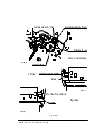
7. Using needle-nose pliers, remove the engagement lever spring. See Figure 6-35.
8. Using a TORX T-10 screwdriver, remove the engagement lever screw from inside
the left sideplate.
9. Remove the spring, lever, and screw from the plotter.
Figure 6-35.
Engagement Lever
Engagement Lever Spring
Screw (Remove
from inside.)
(C)C2858-31b
Summary of Contents for 650c - DesignJet Color Inkjet Printer
Page 1: ...PrinterFAQ COM HP DesignJet650C User Guide ...
Page 126: ...7 10 Adjustments Calibrations Notes ...
Page 156: ...9 4 Product History Notes ...
Page 165: ...10 9 Parts and Diagrams Illustrated Parts Breakdown C2859A Electronics Enclosure C C2858 3 1 ...
Page 167: ...10 11 Parts and Diagrams Illustrated Parts Breakdown C2858A Electronics Enclosure C C2858 4 1 ...
Page 183: ...10 27 Parts and Diagrams Illustrated Parts Breakdown Paper Drive Assemblies C C2858 12 1 ...
Page 199: ......


