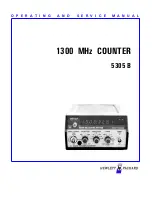
Section
Subsection
Model 5305B
Table of Contents
TABLE OF CONTENTS
Page
iii
I X E
5305B 1300 MHz Counter
I
GENERAL INFORMATION ...................................................................................... 9E-1-1
9E-1-1.
Scope of Manual.................................................................................... 9E-1-1
9E-1-3.
Description ............................................................................................ 9E-1-1
9E-1-6.
Instrument Identification ....................................................................... 9E-1-2
9E-1-8.
Equipment Supplied .............................................................................. 9E-1-2
9E-1-10.
Accessories Available ........................................................................... 9E-1-2
9E-1-12.
5300A/5300B Compatibility. ... ............................................................ 9E-1-2
9E-1-14.
Specifications ........................................................................................ 9E-1-2
9E-1-16.
Recommended Test Equipment............................................................. 9E-1-2
II
INSTALLATION......................................................................................................... 9E-2-1
9E-2-1.
Unpacking and Inspection ..................................................................... 9E-2-1
9E-2-3.
Storage and Shipment............................................................................ 9E-2-1
9E-2-6.
Installation and Removal of Plug-On .................................................... 9E-2-1
9E-2-8.
Portable Operation................................................................................. 9E-2-1
III
OPERATION
9E-3-1
9E-3-1.
Introduction ........................................................................................... 9E-3-1
9E-3-3.
Operating Characteristics ...................................................................... 9E-3-1
9E-3-5.
Input Channels.................................................................................... 9E-3-1
9E-3-9.
Resolution.............................................................................................. 9E-3-1
9E-3-11.
1300 MHz Channel Input Levels........................................................ 9E-3-2
IV
THEORY OF OPERATION ........................................................................................ 9E-4-1
9E-4-1.
Introduction ........................................................................................... 9E-4-1
9E-4-3.
A1 LogicBoard ...................................................................................... 9E-4-1
9E-4-5.
High Impedance Amplifier ................................................................. 9E-4-1
9E-4-12.
Counting Circuits................................................................................ 9E-4-1
9E-4-16.
Frequency Multiplier .......................................................................... 9E-4-2
9E-4-30.
1300 MHz ÷ Circuit............................................................................ 9E-4-4
9E-4-32.
A2 1300 MHz Amplifier Assembly……………………………………9E-4-4
V
MAINTENANCE......................................................................................................... 9E-5-1
9E-5-1.
Introduction ........................................................................................... 9E-5-1
9E-5-3.
Recommended Test Equipment............................................................. 9E-5-1
9E-5-5.
In-Cabinet Performance Check ............................................................. 9E-5-1
9E-5-7.
Instrument Access ................................................................................. 9E-5-1
9E-5-9.
Periodic Maintenance ............................................................................ 9E-5-1
9E-5-11.
Maintenance and Repair ........................................................................ 9E-5-1
9E-5-15.
Adjustments........................................................................................... 9E-5-5
9E-5-17.
Channel A Adjustments......................................................................... 9E-5-5
9E-5-19.
Channel B Adjustments......................................................................... 9E-5-6
9E-5-21.
Troubleshooting..................................................................................... 9E-5-6
9E-5-25.
100 MHz Channel Troubleshooting ...................................................... 9E-5-6
9E-5-27.
1300 MHz Channel Troubleshooting .................................................... 9E-5-7
9E-5-29.
Both Channels Inoperative…………………………………………...9E-5-7
9E-5-34.
Frequency Multiplier .......................................................................... 9E-5-7
VI
REPLACEABLE PARTS ............................................................................................ 9E-6-1
9E-6-1.
Introduction ........................................................................................... 9E-6-1
9E-6-3.
Ordering Information............................................................................. 9E-6-1
Summary of Contents for 5305 B
Page 1: ...O P E R A T I N G A N D S E R V I C E M A N U A L 5305 B 1300 MHz COUNTER ...
Page 21: ...Model 5305B Maintenance STEP A STEP B 9E 5 2 Figure 9E 5 1 Separation Procedure ...
Page 43: ......
Page 47: ......
Page 48: ......


