b.
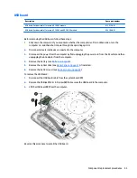
Flex the inside of the top edge (1), the left and right edges (2), and the bottom edge (3) until the
bezel disengages from the display enclosure.
c.
Remove the display bezel (4).
2.
To remove the webcam/microphone module:
a.
Position the display assembly with the top edge toward you.
b.
Lift to disengage the adhesive that secures the webcam/microphone module to the display, and
then remove the module (1) enough to disconnect the cable.
Component replacement procedures
31
Summary of Contents for 340 G3
Page 1: ...HP 340 G3 Notebook HP 346 G3 Notebook HP 348 G3 Notebook Maintenance and Service Guide ...
Page 4: ...iv Safety warning notice ...
Page 22: ...14 Chapter 2 External component identification ...
Page 36: ...28 Chapter 5 Removal and replacement procedures for Customer Self Repair parts ...
Page 54: ...46 Chapter 6 Removal and replacement procedures for Authorized Service Provider parts ...
Page 88: ...80 Chapter 10 Backing up restoring and recovering in Windows 10 ...
Page 106: ...98 Chapter 14 Power cord set requirements ...
Page 108: ...100 Chapter 15 Recycling ...
Page 112: ...104 Index ...


