background image

4-8

Troubleshooting

Diagnosing with the LEDs

LED Patterns for PoE Troubleshooting

If the PoE Status LED is flashing, that indicates a problem with the delivery 
of PoE power out one or more switch ports. Press the LED Mode button to 
put the switch into PoE mode and the port LEDs will show which ports are 
experiencing the problem. The following tables identify the specific problems 
that are shown by the LEDs. 

1.

Check in the table for the LED pattern you see on your switch.

2.

Refer to the corresponding diagnostic tip.
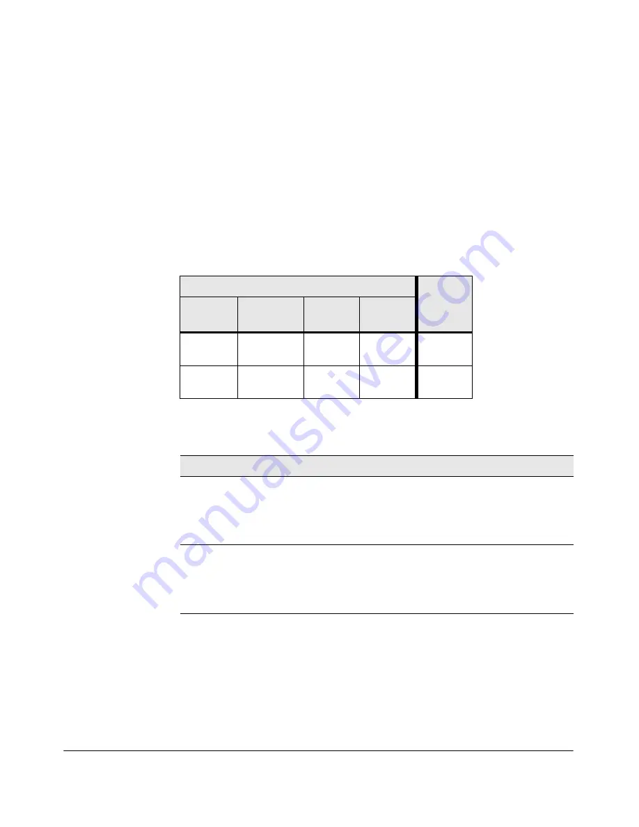
Table 4-2.

LED Error Indicators

Diagnostic Tips:

LED Pattern Indicating Problems

Diagnostic 

Tips

Fault

PoE Status

Port Link

Port Mode

Off Fast 

Flash 

Orange

Slow Flash 

Green

Off

Slow Flash

Slow Flash 

Orange

Slow Flash 

Green

Off

Tip

Problem

Solution

PoE oversubscription 
condition. All available 
PoE power is already 
taken by higher-priority 
ports. 

If possible add additional PoE power, or redefine port 
priorities. 

PoE hardware fault. A 
switch hardware 
component that is 
involved with PoE power 
delivery has failed.

The switch must be replaced. 

Summary of Contents for 2530-24

Page 1: ... 8G J9777A HP 2530 24G J9776A HP 2530 48G J9775A HP 2530 8 PoE J9780A HP 2530 24 PoE J9779A HP 2530 48 PoE J9778A HP 2530 8G PoE J9774A HP 2530 24G PoE J9773A HP 2530 48G PoE J9772A Power over Ethernet HP 2530 Switch Series Installation and Getting Started Guide ...

Page 2: ......

Page 3: ...HP 2530 Switch Series Installation and Getting Started Guide ...

Page 4: ...nal warranty HP shall not be liable for technical or editorial errors or omissions contained herein Hewlett Packard assumes no responsibility for the use or reliability of its software on equipment that is not furnished by Hewlett Packard Warranty For the latest license and warranty information visit www hp com networking support A copy of the specific warranty terms applicable to your Hewlett Pac...

Page 5: ...ower Mode 1 13 2 Installing the Switch Included Parts 2 1 Installation Precautions 2 4 Installation Procedures 2 5 1 Prepare the Installation Site 2 6 2 Verify the Switch Passes Self Test 2 7 LED Behavior 2 8 3 Mount the Switch 2 9 Rack or Cabinet Mounting 2 9 Rack Mounting the Switch 2 10 Wall or Under Table Mounting 2 12 Horizontal Surface Mounting 2 13 4 Connect the Switch to a Power Source 2 1...

Page 6: ...From Here 3 3 Using the IP Address for Remote Switch Management 3 5 Starting a Telnet Session 3 5 Starting a Web Browser Session 3 5 4 Troubleshooting Basic Troubleshooting Tips 4 1 Diagnosing with the LEDs 4 4 LED patterns for General Switch Troubleshooting 4 4 LED Patterns for PoE Troubleshooting 4 8 Proactive Networking 4 9 Hardware Diagnostic Tests 4 10 Testing the Switch by Resetting It 4 10 ...

Page 7: ...onnector Pin Outs A 9 Straight through Twisted Pair Cable for 10 Mbps or 100 Mbps Network Connections A 11 Cable Diagram A 11 Pin Assignments A 11 Crossover Twisted Pair Cable for 10 Mbps or 100 Mbps Network Connection A 12 Cable Diagram A 12 Pin Assignments A 12 Straight Through Twisted Pair Cable for 1000 Mbps Network Connections A 13 Cable Diagram A 13 Pin Assignments A 13 B Safety and EMC Regu...

Page 8: ...vi Contents Safety Information Japan B 6 Safety Information China B 7 EMC Regulatory Statements B 8 U S A B 8 Canada B 8 Australia New Zealand B 8 Japan B 8 Korea B 9 Taiwan B 9 Index ...

Page 9: ...workgroup networks These switches are store and forward devices that offer low latency for high speed networking Six of theswitchesalsosupporttheIEEE802 3atstandardforprovidingPoE power to connected devices HP 2530 8 Switch J9783A HP 2530 24 Switch J9782A HP 2530 48 Switch J9781A HP 2530 8G Switch J9777A HP 2530 24G Switch J9776A ...

Page 10: ...ng the Switch HP 2530 24G PoE Switch J9773A HP 2530 48G Switch J9775A HP 2530 8G PoE Switch J9774A HP 2530 8 PoE Switch J9780A HP 2530 24 PoE Switch J9779A HP 2530 48 PoE Switch J9778A HP 2530 48G PoE Switch J9772A ...

Page 11: ... for supported HP SFP transceivers ports 25 28 The 2530 48G and 2530 48G PoE switches have 48 auto sensing 10 100 1000BASE T RJ 45 ports and four Small Form Factor Pluggable SFP slots for supported HP SFP transceivers ports 49 52 Power over Ethernet or PoE power The HP 2530 PoE switches support the IEEE 802 3at standard which allows IP telephones wireless LAN Access Points and other appliances to ...

Page 12: ...ransceiver Form Factor and Connector1 Speed Technology Cabling SFP Connector 100 Mbps 100 FX Fiber multimode LC 100 BX Fiber single mode LC 1 Gbps 1000 T Copper twisted pair RJ 45 1000 SX Fiber multimode LC 1000 LX Fiber multimode or single mode LC 1000 LH Fiber single mode LC 1000 BX Fiber single mode LC 1 For supported transceivers visit www hp com networking support In the first textbox type J4...

Page 13: ...Ds Switch port LEDs LED Mode select button and indicator LEDs Reset and Clear buttons 10 100 1000BASE T RJ 45 PoE ports1 Console Port 1 All 10 100 1000BASE T RJ 45 ports have the Auto MDIX feature Dual personality ports 10 100 1000BASE T or SFP HP 2530 48 PoE Switch J9778A Power Fault and Locator LEDs Test and Status LEDs Switch port LEDs LED Mode select button and indicator LEDs Reset and Clear b...

Page 14: ...ing 10 100 1000BASE T ports and two SFP slots for fiber or copper uplinks HP 2530 24 port and 48 port Fast Ethernet switches Four SFP slots for fiber or copper uplinks HP 2530 24 port and 48 port Gigabit Ethernet switches LEDs On the 2530 Switches there are three groupings of LEDs switch status LEDs Table 1 2 port LEDs Table 1 3 Port LED Mode indicator LEDs near the selector button Table 1 4 HP 25...

Page 15: ...ously If it is a self test failure the Test LED will be flashing simultaneously When the switch is put in PoE LED Mode the Mode LED for the port with the problem will also be flashing simultaneously One or more ports has an alert condition for PoE delivery for example an oversubscription condition not enough PoE power available Only this LED will be flashing the Fault LED is off When the switch is...

Page 16: ...t The switch Fault and Self Test LEDs will flash simultaneously Mode green 2 Depending on the mode selected displays the following network activity information connection duplex mode connection speed information PoE power delivery status See LED Mode Select Button and Indicator LEDs below for more information SFP LEDs Link2 Flashing green One of the following conditions exist the SFP is not suppor...

Page 17: ... LED shows the port link status in all modes except PoE mode In PoE mode it shows whether the port is configured to provide PoE power The operation of the Mode LED is controlled by the LED Mode select button and the current setting is indicated by the LED Mode indicator LEDs near the button Press the button to step from one view mode to the next The default view is Activity Act Switch LEDs Mode Me...

Page 18: ...console access passwords that you may have configured Use this feature if you have misplaced the password and need console access This button is provided as a convenience however if you areconcernedwiththesecurityoftheswitchconfigurationandoperation you should make sure the switch is installed in a secure location This button can be disabled by a CLI command Restoring Factory Default Configuration...

Page 19: ...tch J9777A HP 2530 8 PoE Switch J9780A HP 2530 8G PoE Switch J9774A AC power connector HP 2530 24 Switch J9782A HP 2530 48 Switch J9781A HP 2530 24G Switch J9776A HP 2530 48G Switch J9775A HP 2530 24 PoE Switch J9779A HP 2530 24G PoE Switch J9773A AC power connector HP 2530 48 PoE Switch J9778A HP 2530 48G PoE Switch J9772A ...

Page 20: ...nsing 10 100BASE TX RJ 45 ports with Auto MDIX Two dual personality ports HP 2530 8 port switches Two auto sensing 10 100 1000BASE T ports and two SFP uplink slots supporting HP SFP transceivers HP 2530 24 port and 48 port Fast Ethernet switches Four SFP uplink slots supporting HP SFP transceivers HP 2530 24 port and 48 port Gigabit Ethernet switches PoE operation the switches are IEEE 802 3at com...

Page 21: ...manage your entire small to medium sized network Intelligent Management Center IMC the HP graphics network management tool intended to manage any sized network IMC support for the HP 2530 switches is planned for early 2013 Go to www hp com networking to check on support availability Support for the Spanning Tree Protocol to eliminate network loops Support for up to 512 IEEE 802 1Q compliant VLANs ...

Page 22: ...1 14 Introducing the Switch Switch Features ...

Page 23: ...egulatory information Software License Warranty and Support information 2530 8 Switch 2530 8G Switch 2530 8 PoE Switch 2530 8G PoE Switch Kit number 5066 2232 Contains two rack mounting brackets eight 8 mm M4 screws to attach the mounting brackets to the switch four 5 8 inch number 12 24 screws to attach the switch to a rack four rubber feet Kit number 5066 0621 Contains three 3 4 20 mm M4 screws ...

Page 24: ...witch to a rack four rubber feet Country Region HP 2530 24 HP 2530 48 HP 2530 24G HP 2530 48G HP 2530 24 PoE and HP 2530 24G PoE HP 2530 48 PoE and HP 2530 48G PoE 1 Argentina Australia New Zealand Brazil Chile China Continental Europe Denmark India Israel Japan Malaysia Switzerland South Africa South Korea Taiwan Thailand United Kingdom Hong Kong Singapore United States Canada Mexico 8120 6869 81...

Page 25: ... 5066 2164 Power Cords Argentina Australia New Zealand Brazil Chile China Continental Europe Denmark India Israel Japan Malaysia Switzerland South Africa South Korea Taiwan Thailand United Kingdom Hong Kong Singapore United States Canada Mexico 8120 8367 8121 0870 8121 1081 8121 0514 8120 8373 8120 6314 8120 6314 8121 0702 8120 6314 8120 6316 8120 8699 8120 6314 8120 6317 8120 6314 8121 0963 8121 ...

Page 26: ...n damage to the equipment For those switches that use a power cord if your installation requires a different power cord than the one supplied with the switch be sure to use a power cord displaying the mark of the safety agency the defines the regulations for power cords in your country The mark is your assurance that the power cord can be used safely with the switch Ensure the switch does not over...

Page 27: ... 4 Connect power to the switch page 2 14 Once the switch is mounted plug it into the main power source 5 Connect the network devices page 2 16 Using the appropriate network cables connect the network devices to the switch ports 6 Optional Install SFP transceivers page 2 17 The switch has four slots for installing SFP transceivers Depending on where you install the switch it may be easier to instal...

Page 28: ... Specifications for more information Installation Location Before installing the switch plan its location and orientation relative to other devices and equipment In the front of the switch leave at least 7 6 cm 3 inches of space for the twisted pair and fiber optic cabling In the back of the switch leave at least 3 8 cm 1 1 2 inches of space for the power cord On the sides of the switch leave at l...

Page 29: ...iedwith theswitch tothe power connectoron the back ofthe switch and then into a properly grounded electrical outlet For the HP 2530 8 port switches connect the AC DC adapter s power cord to the power connector on the back of the switch and then plug the AC DC power adapter into a nearby properly grounded electrical outlet Figure 2 1 Connecting the power cord Connect power cord to the power connect...

Page 30: ...al AC DC power adapter is connected to the switch and the adapter power cord to a power source The external AC DC power adapter automatically adjusts to any voltage between 100 240 volts and either 50 or 60 Hz 2 Check the LEDs on the switch as described below Figure 2 2 Checking the LEDs When the switch is powered on it performs its diagnostic self test Self test takes approximately 50 seconds to ...

Page 31: ...s not completed correctly Refer to chapter 4 Troubleshooting for diagnostic help 3 Mount the Switch After the switch passes self test it is ready to be mounted in a stable location The switch can be mounted in these ways in a rack or cabinet on a horizontal surface under a table on a wall Rack or Cabinet Mounting The switch is designed to be mounted in any EIA standard 19 inch telco rack or commun...

Page 32: ...ch Rack Mounting the Switch 1 Use a 1 Phillips cross head screwdriver and attach the mounting brackets to the switch with the included 8 mm M4 screws Figure 2 3 Attaching mounting brackets WARN I NG For safe reliable installation only use the screws provided in the accessory kit to attach the mounting brackets to the switch Not e The mounting brackets have multiple mounting holes and can be rotate...

Page 33: ...d the switch with attached brackets up to the rack and move it vertically until rack holes line up with the bracket holes then insert and tighten the four number 12 24 screws holding the brackets to the rack Figure 2 4 Mounting in a rack Install 12 24 screws ...

Page 34: ...n or fan ducts facing up or down C a u t i o n The switch should be mounted only to a wall or wood surface that is at least 1 2 inch 12 7 mm plywood or its equivalent To mount the HP 2530 24 port and 48 port switches follow these steps 1 Use a 1 Phillips cross head screwdriver and attach the mounting brackets to the switch with the included 8 mm M4 screws 2 Attach the switch to the wall or wood su...

Page 35: ... 6 Wall mounting the 8 port switches 3 For under table mounting a third 20 mm M4 tap screw can be placed against one side of the switch to secure it in place Horizontal Surface Mounting Place the switch on a table or other horizontal surface The switch comes with rubber feet in the accessory kit that can be used to help keep the switch from sliding on the surface Attach the rubber feet to the four...

Page 36: ...cord into the switch s power connector and into a nearby AC power source For the HP 2530 8 port switches plug the AC DC adapter s power cord into the switch and then plug the AC DC power adapter into a nearby AC power source Figure 2 7 Connecting the power cord on the 2530 48G PoE Switch 2 Re check the LEDs during self test See LED Behavior on page 2 8 3 For the HP 2530 8 port switches use the inc...

Page 37: ...igure 2 8 Using the cable tie on the HP 2530 8 port switches Not e The HP 2530 8 port switches include an optional power shelf HP P N J9820A to hold the AC DC power adapter For instructions on how to install this accessory see the included documentation ...

Page 38: ...ondevice for example an end node is at the other end of the cable If the Link LED does not go on when the network cable is connected to the port see Diagnosing with the LEDs in chapter 4 Troubleshooting To disconnect Press the small tab on the plug and pull the plug out of the port Not e The HP 2530 8 port switches include an optional cable guard HP P N J9700A to provide security for the attached ...

Page 39: ...e s Ensure the network cable is NOT connected when you install or remove an SFP C a u t i o n Use only supported genuine HP SFPs with your switch Non HP SFPs are not supported and their use may result in product malfunction Should you require additional HP SFPs contact your HP Networking Sales and Service Office or authorized dealer Installing the SFPs Remove the protective plastic cover and retai...

Page 40: ...you will need to use depends on the type of SFPs you have installed See the table on page 1 4 and appendix A Specifications for the SFP cabling information For SFP ports and in general for all the switch ports when a network cable from an active network device is connected to the port the port Link LED for that port should go on If the port Link LED does not go on when the network cable is connect...

Page 41: ...econnect it to a live PC In Band Access the console using Telnet from a PC or UNIX station on the network and a VT 100 terminal emulator This method requires that you first configure the switch with an IP address and subnet mask by using either out of band console access or through DHCP Bootp For more information on IP addressing and on starting a Telnet session see chapter 3 Configuring the Switc...

Page 42: ...elect one of the switches from the drop down list Click the Display selected button From the options that appear select Software downloads on the right hand side Download the USB Console Port Drivers and Information Direct Console Access To connect a console to the switch follow these steps 1 Connect the PC or terminal to the switch s Console Port using the console cable included with the switch I...

Page 43: ...sole command CLI prompt for example HP 2530 24G PoEP If you want to continue with console management of the switch at this time see chapter 3 Getting Started With Switch Configuration for some basic configuration steps For more detailed information refer to the Management and Configuration Guide which is on the HP Web site at www hp com networking support Optional USB Console cable not supplied Co...

Page 44: ...Figure 2 12 Basic desktop configuration The HP 2530 PoE switches are designed to be used as desktop switches to which end nodes printers and other peripherals and servers are directly connected as shown in the above illustration The switches can also supply PoE power to end devices such as IP telephones HP 2530 48G PoE Twisted pair straight through or crossover cables Server with Gigabit Ethernet ...

Page 45: ...traight through or crossover twisted pair cables Either cable type can be used because of the Auto MDIX feature on the HP 2530 Switches As a Segment Switch Implementing PoE Figure 2 13 Segment network configuration with PoE switches The HP 2530 Switches also work well as segment switches That is with their high performance they can be used for interconnecting network segments simply connect the ne...

Page 46: ... from each of the switches Only devices directly connected to PoE switches can receive PoE power Devices connected to the non PoE switch cannot receive PoE power Because the HP 2530 Switches have the Auto MDIX feature the connections between the switches and end nodes or servers can be through category 5 straight through or crossover twisted pair cable Category 3 or 4 cable can also be used if the...

Page 47: ...530 Switch as the Commander and give that switch an IP address Up to 15 other switches in the network can then easily be configured as Members of the stack and managed through the Commander s IP address The management includes Telnet access and Web browser interface access to the Commander and to each Member switch through the Commander For more information on stacking your switch see the Manageme...

Page 48: ...2 26 Installing the Switch Sample Network Topologies ...

Page 49: ...r interface Other parameters in the Switch Setup screen can be left at their default settings or you can configure them with values you enter Many other features can be configured through the switch s console interface to optimize the switch s performance to enhance your control of the network traffic and to improve network security Once an IP address has been configured on the switch these featur...

Page 50: ... default display The CLI prompt appears for example HP 2530 24G PoEP 2 At the prompt enter the setup command to display the Switch Setup screen The following illustration shows the Setup screen with the default settings Figure 3 1 Example console setup screen 3 Use the Tab key to select the Manager Password field and enter a manager password of up to 16 printable ASCII characters 4 Tab to the IP C...

Page 51: ... the menu interface Time Zone 0 none Optional 1440 to 1440 The number of minutes your location is to the West or East of GMT Community Name public Default setting recommended Spanning Tree Enabled No Default setting recommended unless STP is already running on your network or the switch will be used in complex network topologies Default Gateway blank Optional Enter the IPaddressofthenext hopgatewa...

Page 52: ...ver from a Lost Manager Password If you cannot start a console session at the manager level because of a lost Manager password you can clear all passwords and user names by getting physical access to the switch and pressing and holding the Clear button for a full second ...

Page 53: ...hen see the switch console command CLI prompt for example HP 2530 24G PoEP Enter help or to see a list of commands that can be executed at the prompt Entering any command followed by help provides more detailed context help information about the command Entering any command followed by displays a list of options that are available at that point in the command entry Starting a Web Browser Session T...

Page 54: ...3 6 Configuring the Switch Using the IP Address for Remote Switch Management ...

Page 55: ...diagnostic tests page 4 10 restoring the factory default configuration page 4 12 downloading new software to the HP 2530 Switches page 4 13 HP Customer Support Services page 4 13 Basic Troubleshooting Tips Most problems are caused by the following situations Check for these items first when starting your troubleshooting Connecting to devices that have a fixed full duplex configuration The RJ 45 po...

Page 56: ...on Improper Network Topologies It is important to make sure you have a valid network topology Common topology faults include excessive cablelengthandexcessiverepeaterdelaysbetweenendnodes Ifyouhave network problems after recent changes to the network change back to the previous topology If you no longer experience the problems the new topology is probably at fault Sample topologies are shown at th...

Page 57: ...king Note that the normal operation of the Spanning Tree GVRP and LACP features may put the port in a blocking state Or the port just may have been configured as disabled through software Use the switch console to determine the port s configuration and verify that there is not an improper or undesired configuration of any of the switch features that may be affecting the port For more information s...

Page 58: ...ee on your switch 2 Refer to the corresponding diagnostic tip on the next few pages Table 4 1 LED Error Indicators LED Pattern Indicating Problems Diagnostic Tips Power Fault Test Fan Port Link LED Off with powercord plugged in 1 1 1 1 On Prolonged On Prolonged On 1 1 On Flashing2 Flashing2 1 1 On Flashing2 Off Flashing2 1 On Flashing2 Flashing2 1 Flashing2 On Off Off 1 Off with cable connected On...

Page 59: ...ition You can view the console log at that point by selecting it from the console Main Menu or by typing Show log at the Manager command prompt If necessary to resolve the problem contact your HP authorized network reseller or use the electronic support services from HP to get assistance Oneoftheswitch cooling fans may have failed Try disconnecting power from the switch and wait a few moments Then...

Page 60: ...t on the connected device and the switch receive port is connected to the transmit port on the connected device For 1000BASE T connections verify the network cabling complies with the IEEE 802 3ab standard The cable should be installed according to the ANSI TIA EIA 568 A 5 specifications Cable testing should comply with the stated limitations for Attenuation Near End Crosstalk Far End Crosstalk Eq...

Page 61: ...plays the port status for Spanning Tree Also check the Port Status screen using the show interfaces command to see if the port has been configured as disabled Other switch features that may affect the port operation include VLANs and IGMP Use the switch console to see how the port is configured for these features For software troubleshooting tips seethechapter Troubleshooting inthe Management and ...

Page 62: ...e table for the LED pattern you see on your switch 2 Refer to the corresponding diagnostic tip Table 4 2 LED Error Indicators Diagnostic Tips LED Pattern Indicating Problems Diagnostic Tips Fault PoE Status Port Link Port Mode Off Fast Flash Orange Slow Flash Green Off Slow Flash Slow Flash Orange Slow Flash Green Off Tip Problem Solution PoE oversubscription condition All available PoE power is a...

Page 63: ...h and its network connections and to help you take advantage of these proactive networking features A graphical Web browser interface you can use to manage your switch from a PC running a supported Web browser for example Microsoft Internet Explorer and Netscape Communicator Afull featuredeasy to useconsoleinterfaceyoucanaccessbyconnecting a standard terminal or PC running a terminal emulator to t...

Page 64: ...ront of the switch go off after approximately 50 seconds If these LEDs stay on longer than 60 seconds or begin flashing there may be a problem with the switch See Diagnosing with the LEDs on page 4 4 for information on interpreting the LED patterns Checking Console Messages Useful diagnostic messages may be displayed on the console screen when the switch is reset As described in chapter 2 under st...

Page 65: ...ed by its MAC address Ping Test a network layer test used on IP networks that sends test packets to any device identified by its IP address These tests can be performed through the switch console interface from a terminal connected to the switch or through a Telnet connection or from the switch s Web browser interface For more information see the Management and Configuration Guide which is on the ...

Page 66: ...tion problems you should save the switch configuration prior to performing the factory default reset Then after the reset and resolution of the original problem you can restore the saved configuration to the switch For both the save and restore processes you can use the console copy command For more information on this command see the Management and Configuration Guide which is on the HP Web site ...

Page 67: ...ng support also provides up to date support information Additionally your HP authorized network reseller can provide you with assistance both with services that they offer and with services offered by HP Before Calling Support Before calling your networking dealer or HP Support to make the support process most efficient you first should retrieve the following information Information Item Informati...

Page 68: ...4 14 Troubleshooting HP Customer Support Services ...

Page 69: ...1 cm 9 7 in 4 4 cm 1 73 in 4 39 kg 9 66 lbs 2530 48G J9775A 44 3 cm 17 4 in 24 61 cm 9 7 in 4 4 cm 1 73 in 4 68 kg 10 30 lbs 2530 8 PoE J9780A 25 4 cm 10 in 15 95 cm 6 28 in 4 4 cm 1 73 in 2 21 kg 4 87 lbs 2530 24 PoE J9779A 44 3 cm 17 4 in 32 26 cm 12 7 in 4 4 cm 1 73 in 4 38 kg 9 66 lbs 2530 48 PoE J9778A 44 3 cm 17 4 in 32 26 cm 12 7 in 4 4 cm 1 73 in 5 07 kg 11 18 lbs 2530 8G PoE J9774A 25 4 c...

Page 70: ... 2530 48 J9781A 2 100 127 volts 200 240 volts 0 70 A 0 40 A 50 60 Hz 2530 8G J9777A 1 100 240 volts 0 50 A 50 60 Hz 2530 24G J9776A 2 100 127 volts 200 240 volts 0 60 A 0 37 A 50 60 Hz 2530 48G J9775A 2 100 127 volts 200 240 volts 1 20 A 0 68 A 50 60 Hz 2530 8 PoE J9780A 1 100 240 volts 1 40 A 50 60 Hz 2530 24 PoE J9779A 2 100 127 volts 200 240 volts 2 80 A 1 40 A 50 60 Hz 2530 48 PoE J9778A 2 100...

Page 71: ...IN 45635 T 19 Noise Emission LpA 34 0 dB at virtual workspace according to DIN 45635 T 19 2530 48G J9775A Geraeuschemission LpA 34 5 dB am fiktiven Arbeitsplatz nach DIN 45635 T 19 Noise Emission LpA 34 5 dB at virtual workspace according to DIN 45635 T 19 2530 24 PoE J9779A Geraeuschemission LpA 40 1 dB am fiktiven Arbeitsplatz nach DIN 45635 T 19 Noise Emission LpA 40 1 dB at virtual workspace a...

Page 72: ...100 FX IEEE 802 3u 100BASE FX EN IEC 60825 Class 1 Laser Product Laser Klasse 1 100 BX IEEE 802 3ah 100BASE BX10 EN IEC 60825 Class 1 Laser Product Laser Klasse 1 1000 SX IEEE 802 3z 1000BASE SX EN IEC 60825 Class 1 Laser Product Laser Klasse 1 1000 LX IEEE 802 3z 1000BASE LX EN IEC 60825 Class 1 Laser Product Laser Klasse 1 1000 LH not an IEEE standard EN IEC 60825 Class 1 Laser Product Laser Kla...

Page 73: ... cables that connect the switch and other end devices to the patch panels on your site The patch cables are frequently overlooked when testing cable and they must also comply with the cabling standards Table A 2 Cabling Specifications Twisted pair copper 10 Mbps Operation Category 3 4 or 5 100 ohm unshielded twisted pair UTP or shielded twisted pair STP cable complying with IEEE 802 3 10BASE T spe...

Page 74: ...ed pair copper N A up to 100 meters 1000 SX multimode fiber 160 MHz km 200 MHz km 400 MHz km 500 MHz km 2 220 meters 2 275 meters 2 500 meters 2 550 meters 1000 LX multimode fiber single mode fiber 400 MHz km 500 MHz km N A 2 550 meters 2 550 meters 2 10 000 meters 1000 LH single mode fiber N A 10 70 000 meters1 1000 BX single mode fiber N A 0 5 10 000 meters 1 Fordistances less than 20km a 10dB a...

Page 75: ...cabling at both ends of the network link The patch cord consists of a short length of single mode fiber cable coupled to graded index multimode fiber cable on the transmit side and only multimode cable on the receive side The section of single mode fiber is connected in such a way that it minimizes the effects of the differential mode delay in the multimode cable Not e Most of the time if you are ...

Page 76: ...teristics of the multimode fiber in your network Most important the core diameter of the multimode patch cord must match the core diameter of the multimode cable infrastructure either 50 or 62 5 microns Tx Rx To network multimode cabling Mode Conditioning Patch Cord The multimode cable in the patch cord mustmatchthecharacteristicsofyour network cable Gigabit LX port Single mode section plugs into ...

Page 77: ...straight through cables or crossover cables If you happen to use a correctly wired crossover cable though the switch will still be able to automatically detect the MDI MDI X operation and link correctly to the connected device Not e Using Fixed Configurations If the port configuration is changed to any of the fixed configurations though for example 100 Mbps full duplex the port operates as MDI X o...

Page 78: ...s supported by the IEEE 802 3u Type 100BASE TX standard For 1000 Mbps connections 100 ohm Category 5e or better cabling is recommended To provide Power over Ethernet to the access point all 4 pairs must be connected for any network cable attached to this port the cable must meet ISO DIS 11801 Class D requirements and IEEE 802 3af requirements ...

Page 79: ...ps Full Duplex the ports operate as MDI X ports and straight through cables must be then used for connections to PC NICs and other MDI ports Cable Diagram Not e Pins 1 and 2 on connector A must be wired as a twisted pair to pins 1 and 2 on connector B Pins 3 and 6 on connector A must be wired as a twisted pair to pins 3 and 6 on connector B Pins 4 5 7 and 8 are not used in this application althoug...

Page 80: ... ports operate as MDI X ports and crossover cables must be then used for connections to hubs or switches or other MDI X network devices Cable Diagram Not e Pins 1 and 2 on connector A must be wired as a twisted pair to pins 3 and 6 on connector B Pins 3 and 6 on connector A must be wired as a twisted pair to pins 1 and 2 on connector B Pins 4 5 7 and 8 are not used in this application although the...

Page 81: ...tor A must be wired as a twisted pair to pins 1 and 2 on connector B Pins 3 and 6 on connector A must be wired as a twisted pair to pins 3 and 6 on connector B Pins 4 and 5 on connector A must be wired as a twisted pair to pins 4 and 5 on connector B Pins 7 and 8 on connector A must be wired as a twisted pair to pins 7 and 8 on connector B Pin Assignments For 1000BASE T operation all four pairs of...

Page 82: ...A 14 Specifications Twisted Pair Cable Connector Pin Outs ...

Page 83: ...ent volt ages such as lightning or disturbances in the electrical utilities power grid Handle exposed metalcomponents ofthe network with caution Servicing There are no user serviceable parts inside these products Any servicing adjustment maintenance or repair must be performed only by service trained personnel These products do not have a power switch they are powered on when the power cord is plu...

Page 84: ...nsions transitoires dangereuses telles que la foudre ou des perturba tions dans le réseau d alimentation public Manipulez les composants métalliques du réseau avec précautions Aucune pièce contenue à l intérieur de ce produit ne peut être réparée par l utilisateur Tout dépannage réglage entretien ou réparation devra être confié exclusivement à un personnel qualifié Cet appareil ne comporte pas de ...

Page 85: ... werden beispielsweise durch Blitz oder Störungen in dem Starkstromnetz des Elektrizitätswerks Bei der Handhabung exponierter Metallbestandteile des Netzwerkes Vorsicht walten lassen Dieses Gerät enthält innen keine durch den Benutzer zu wartenden Teile Wartungs Anpassungs Instandhaltungs oder Reparaturarbeiten dürfen nur von geschultem Bedienungspersonal durchgeführt werden Dieses Gerät hat keine...

Page 86: ...vi LAN possono occasionalmente andare soggetti a pericolose tensioni transitorie ad esempio provocate da lampi o disturbi nella griglia d alimen tazione della società elettrica siate cauti nel toccare parti esposte in metallo della rete Nessun componente di questo prodotto può essere riparato dall utente Qualsiasi lavoro di riparazione messa a punto manutenzione o assistenza va effettuato esclusi ...

Page 87: ...que los cables de la LAN se vean sometidos de vez en cuando a voltajes momentáneos que entrañen peligro rayos o alteraciones en la red de energía eléctrica Manejar con precaución los componentes de metal de la LAN que estén al descubierto Este aparato no contiene pieza alguna susceptible de reparación por parte del usuario Todas las reparaciones ajustes o servicio de mantenimiento debe realizarlos...

Page 88: ...B 6 Safety and EMC Regulatory Statements Safety Information Japan Safety Information Japan J a p a n P o w e r C o r d Wa r n i n g ...

Page 89: ...B 7 Safety and EMC Regulatory Statements Safety Information China Safety Information China ...

Page 90: ...n a commercial environment This equipment gener ates uses and can radiate radio frequency energy and if not installed and used in accordance with the instruction manual may cause interference to radio communications Operation of this equipment in a residential area may cause interference in which case the user will be required to correct the interference at his own expense Canada This product comp...

Page 91: ...B 9 Safety and EMC Regulatory Statements EMC Regulatory Statements Korea Taiwan ...

Page 92: ...B 10 Safety and EMC Regulatory Statements EMC Regulatory Statements ...

Page 93: ...ts 2 16 effects of non standard cables 4 2 infrastructure requirements 2 6 serial for direct console connection 2 20 cables twisted pair category 3 4 5 A 9 cross over cable pin out A 12 MDI X to MDI connections A 11 A 13 MDI X to MDI X connections A 12 pin outs A 11 A 13 straight through cable pin out A 11 A 13 switch to computer connection A 11 A 13 switch to switch or hub connection A 12 cables ...

Page 94: ...A 3 EMC regulatory statements B 8 environmental specifications switch A 3 F factory default configuration restoring 1 10 4 12 Fan Status LED 1 7 Fault LED 1 7 behavior during self test 2 9 behaviors 1 7 flashing definition 1 7 1 8 location on switch 1 5 showing error conditions 4 4 features console 2 18 switch 1 12 fiber optic cables 1000Base BX A 6 1000Base LH A 6 1000Base T A 6 flashing LEDs err...

Page 95: ...tor pin outs A 9 twisted pair wiring rules A 9 network devices connecting to the switch 2 16 network ports connecting to 2 16 location on switch 1 6 types of 1 6 non standard network cables effects 4 2 O out of band console access 3 5 P parts included with the switch 2 1 password configuring 3 2 passwords deleting with the Clear button 3 4 if you lose the password 3 4 passwords deleting 1 10 physi...

Page 96: ... 2 A 3 environmental A 3 physical A 1 safety A 3 straight through cable pin out A 11 A 13 subnet mask configuring 3 2 switch connecting to a power source 2 14 description 1 1 downloading new software 4 13 electrical specifications A 2 A 3 environmental specifications A 3 features 1 12 front panel description 1 5 included parts 2 1 LED descriptions 1 7 mounting in a rack or cabinet 2 9 mounting on ...

Page 97: ...storing factory default configuration 4 12 testing connections to other devices 4 11 testing end to end communications 4 11 testing the switch 4 10 testing the twisted pair cables 4 11 twisted pair cable cross over cable pin out A 12 pin outs A 9 A 11 A 13 straight through cable pin out A 11 A 13 switch to computer connection A 11 A 13 switch to switch or hub connection A 12 testing 4 11 twisted p...

Page 98: ......

Page 99: ... herein is subject to change without notice The only warranties for HP products and services are set forth in the express warranty statements accompanying such products and services Nothing herein should be construed as constituting an additional warranty HP will not be liable for technical or editorial errors or omissions contained herein June 2013 Manual Part Number 5998 3094 ...

Reviews: