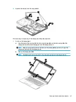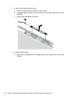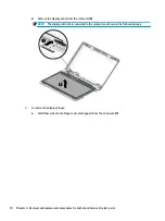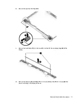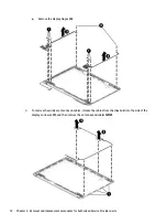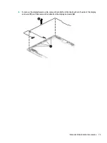
7.
Use the following image to determine proper cable routing around the hinges.
8.
If replacing the display enclosure, be sure that the subcomponents (including the camera/microphone
module, the antenna receivers, and all associated cables and hardware) are transferred to the new
enclosure.
Reverse this procedure to reassemble and install the display assembly.
74
Chapter 6 Removal and replacement procedures for Authorized Service Provider parts
Summary of Contents for 14-BS0 Series
Page 1: ...HP 14 Laptop PC Intel HP 14g Laptop PC HP 14q Laptop PC Maintenance and Service Guide ...
Page 4: ...iv Safety warning notice ...
Page 8: ...viii ...
Page 14: ...Category Description AC adapter Battery Optical drive 6 Chapter 1 Product description ...
Page 34: ...26 Chapter 3 Illustrated parts catalog ...
Page 44: ...36 Chapter 5 Removal and replacement procedures for Customer Self Repair parts ...
Page 86: ...78 Chapter 6 Removal and replacement procedures for Authorized Service Provider parts ...
Page 94: ...86 Chapter 8 Backing up restoring and recovering ...
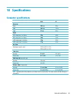
Page 102: ...94 Chapter 10 Specifications ...
Page 106: ...98 Chapter 11 Power cord set requirements ...
Page 108: ...100 Chapter 12 Recycling ...
Page 112: ...104 Index ...


