HP
11757B
Installation
and
Calibration
parameters
are
set
to
45
MHz
and
95
MHz,
but
sw
eep
is
set
to
o.
FREQ
=
70
MHz
Start
Sw
eep
=
45
MHz
Stop
Sw
eep
=
95
MHz
DEPTH
=
0
dB
A
TTEN
=
0
dB
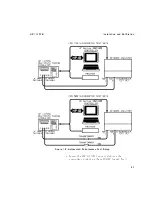
3.
Connect
the
output
of
the
signal
generator
to
the
IF
Input
of
the
F
ader.
Use
a
75
cable,
with
an
adapter
at
the
syn
thesized
sw
eep er
output.
Note
Use
Video
T
rigger
on
the
sp ectrum
analyzer
to
set
a
stable
trace.
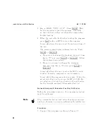
4.
Connect
the
IF
Output
of
the
F
ader
to
the
input
of
the
sp ectrum
analyzer.
Use
a
75
cable
with
an
adapter
at
the
sp ectrum
analyzer.
5.
Set
notc
h
depth
to
20
dB.
Press
4
NOTCH
DEPTH
5
Press
4
2
5
4
0
5
4
ENTER
5
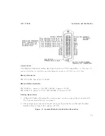
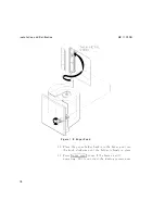
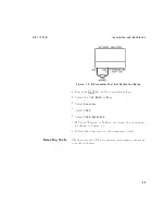
Figure
1-7.
Front
P
anel
Checks
Setup
23

