background image

front_757_58.fm5    i  Tue Oct 20 16:05:31 1998

HP 11757B

Multipath Fading Simulator

Installation and Calibration Guide

HP Part No.  11757-90058

Printed in UK

October 1998

© Copyright Hewlett-Packard Ltd. 1998

Summary of Contents for 11757B

Page 1: ...hat previously shipped under the Hewlett Packard company brand name The brand name has now been changed to Agilent Technologies The two products are functionally identical only our name has changed The document still includes references to Hewlett Packard products some of which have been transitioned to Agilent Technologies ...

Page 2: ...front_757_58 fm5 i Tue Oct 20 16 05 31 1998 HP 11757B Multipath Fading Simulator Installation and Calibration Guide HP Part No 11757 90058 Printed in UK October 1998 Copyright Hewlett Packard Ltd 1998 ...

Page 3: ... use of this material This document contains proprietary information which is protected by copyright All rights are reserved No part of this document may be photocopied or reproduced without the prior written consent of the manufacture Hewlett Packard Ltd Copyright Hewlett Packard Ltd 1998 All Rights Reserved Reproduction adaptation or translation without prior written permission is prohibited exc...

Page 4: ...8950 Japan tel 81 426 56 7832 fax 81 426 56 7840 Australia tel 1 800 629 485 fax 61 3 9210 5947 Asia Call Center Numbers Country Phone Number Fax Number Singapore 1 800 375 8100 65 836 0252 Malaysia 1 800 828 848 1 800 801664 Philippines 632 8426802 1 800 16510170 PLDT Subscriber Only 632 8426809 1 800 16510288 PLDT Subscriber Only Thailand 088 226 008 outside Bangkok 662 661 3999 within Bangkok 6...

Page 5: ...ements of European Council Directive 89 336 EEC on the approximation of the laws of the member states relating to electromagnetic compatibility against EMC test specifications EN 55011 1991 Group 1 Class A and EN 50082 1 1992 As Detailed in Electromagnetic Compatibility EMC Technical Construction File TCF No A 5951 9852 02 Assessed by DTI Appointed Competent Body EMC Test Centre GEC Marconi Avioni...

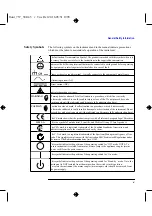
Page 6: ...rrent rating and type DO NOT perform procedures involving cover or shield removal unless you are qualified to do so Operating personnel must not remove equipment covers or shields Procedures involving the removal of covers and shields are for use by service trained personnel only DO NOT service or adjust alone Under certain conditions dangerous voltages may exist even with the equipment switched o...

Page 7: ...ctly performed or adhered to could result in damage to or destruction of the instrument Do not proceed beyond a caution note until the indicated conditions are fully understood and met The CE mark shows that the product complies with all relevant European Legal Directives ISM 1 A This is a symbol of an Industrial Scientific and Medical Group 1 Class A product The CSA mark is a registered trademark...

Page 8: ... cable set WARNING Any interruption of the protective grounding conductor inside or outside the system or disconnecting the proctective earth terminal will cause a potential shock hazard the could result in personel industry Grounding one conductor of a two conductor outlet is not sufficient protection In addition verify that a comon ground exists between the unit under test and the system prior t...

Page 9: ...zardous electrical shock do not turn on the instrument when there are signs of shipping damage to any portion of the outer enclosure covers panels display Inspect the shipping container for damage If the shipping container or cushioning material is damaged it should be kept until the contents of the shipment have been checked for completeness and the instrument has been checked mechanically and el...

Page 10: ...be provided from the main power source to the product input wiring terminals through the power cable or supplied power cable set Whenever it is likely that the protection has been impaired the product must be made inoperative and be secured against any unintended operation If this instrument is to be energized via an external autotransformer make sure the autotransformer s common terminal is conne...

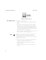
Page 11: ...der requires a power source of 115 or 230 610 Vac 50 to 60 Hz Power consumption is 200 VA Line Voltage Selection Caution BEFORE PLUGGING THIS INSTRUMENT into the line Mains voltage make sure that the correct operating voltage and fuse has been selected 1 On the rear panel of the Fader is a red recessed switch for selecting the operating voltage It is labeled Voltage Selector Check the switch setti...

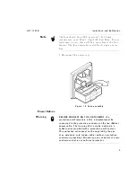
Page 12: ... center prong ground is a tab At the bottom of the plastic receptacle is another tab 3 With your ngers or a small athead screwdriver pull back on the tabs The drawer will open Note The fuse is disconnected from the circuit when the drawer is opened You can check the fuse with a continuity light to see if it has opened without removing the fuse from the drawer 4 Using a screwdriver push either end ...

Page 13: ...Fuse assembly Power Cables Warning BEFORE CONNECTING THIS INSTRUMENT the protective earth terminals of this instrument must be connected to the protective conductor of the line Mains power cable The line plug shall only be inserted in a socket outlet provided with a protective earth contact The protective action must not be negated by the use of an extension cord power cable without a protective c...

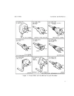
Page 14: ...he type of power cable plug shipped with each instrument depends on the country of destination See gure 1 3 Power Cable and Line Mains Plug Part Numbers for the part numbers of these power cables Cables are available in di erent lengths and some with right angle plugs to the instrument Check with your nearest Hewlett Packard service center for descriptions and part numbers for these cables 6 ...

Page 15: ...HP 11757B Installation and Calibration Figure 1 3 Power Cable and Line Mains Plug Part Numbers 7 ...

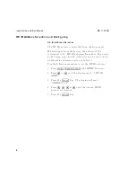
Page 16: ...es from 00 to 30 as well as 40 listen only and 50 talk only can be used A list of allowable addresses is given in table 1 1 Use the following procedure to set the HP IB address 1 Press 4SHIFT5 4PRESET LOCAL5 the MORE function 2 Press 485 or 495 until the display reads 5 HP IB ADRS 3 Press the 4ENTER5 key The display will read ADDRESS 14 4 Press 485 495 465 or 475 until the desired HP IB address is...

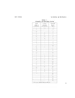
Page 17: ...Codes Talk Address Character Listen Address Character Decimal Equiv alent SP 0 A 1 B 2 C 3 D 4 E 5 F 6 G 7 H 8 I 9 J 10 K 11 L 12 M 13 N 14 1 O 15 P 0 16 Q 1 17 R 2 18 S 3 19 T 4 20 U 5 21 V 6 22 W 7 23 X 8 24 Y 9 25 Z 26 27 g 28 29 30 1Factory set Fading Simulator address 9 ...

Page 18: ...n data for the Hewlett Packard Interface Bus is provided in gure 1 4 Hewlett Packard Interface Bus Connection HP IB Interface Connector The HP IB mating connector is shown in gure 1 4 Hewlett Packard Interface Bus Connection Note that the two securing screws are metric 10 ...

Page 19: ...30240 Mating Cables Available HP 10833A 1 metre 3 3 ft HP 10833B 2 metres 6 6 ft HP 10833C 4 metres 13 2 ft HP 10833D 0 5 metre 1 6 ft Cabling Restrictions 1 A Hewlett Packard Interface Bus system may contain no more than 2 metres 6 6 ft of connecting cable per instrument 2 The maximum accumulative length of connecting cable for any Hewlett Packard Interface Bus system is 20 0 metres 65 6 ft Figur...

Page 20: ...ution Do not input power exceeding 20 dBm to the IF Input of the Fader This could damage the instrument Error Pulse Input The error pulse input is internally con gurable to the following ECL 75 default TTL 75 TTL 10k Variable threshold 2 volt termination 75 Variable threshold 0 volt termination 75 Variable threshold 0 volt termination 10k To make the appropriate setting press the 4RADIO SETUP5 key...

Page 21: ...art number 9270 1299 To load a new roll of paper into the Fader Caution Never pull the paper from the Fader Use the 4PAPER FEED5 key Failure to do so could cause permanent damage to the print head 1 The Fader must be plugged in and the power switch set to on 2 Turn the knob on the paper holder counter clockwise several times until the paper holder can be pulled out of the Fader 3 Slide the paper c...

Page 22: ...tallation and Calibration HP 11757B 7 Place the paper cover back on and pull some paper out on the side of the cover closest to the paper feeder Figure 1 5 Paper Holder 8 Cut the end of the paper square 14 ...

Page 23: ...per scrolls through the paper tear at the front of the Fader Note The paper slot may be hard for some users to see It consists of a black plastic feed and a metal backing The paper must be placed between these parts and as parallel to the base of the instrument as possible If you experience di culty try examining the feed and backing with a ashlight rst 15 ...

Page 24: ... Figure 1 6 Paper Feed 10 Place the paper holder back into the Fader and turn the knob clockwise until the holder is rmly in place 11 Press 4PAPER FEED5 to see if the feeder is still operating If it is not start the loading process over 16 ...

Page 25: ...mounting kits are as follows Without Handles 5062 4840 With Handles 5062 4841 Storage and Shipment Environment The instrument should be stored in a clean dry environment The following environmental limitations apply to both storage and shipment Temperature 055 C to 75 C Humidity 95 relative Altitude 15 300 metres 50 000 feet Packaging Tagging for Service If the instrument is being returned to Hewl...

Page 26: ...age careful handling In any correspondence refer to the instrument by model number and full serial number Other Packaging The following general instructions should be used for repackaging with commercially available materials 1 Wrap the instrument in heavy paper or plastic If shipping to a Hewlett Packard o ce or service center complete one of the blue tags mentioned above and attach it to the ins...

Page 27: ...cause a potential shock hazard that could result in personal injury Caution Before the Fader is switched on it must be set to the same line voltage as the power source or damage to the instrument may result Refer to the Installation Guide for instructions Turn On Procedure If the power cable is not plugged in follow these instructions On the rear panel 1 Check the line voltage selection switch for...

Page 28: ...z for option 140 0 dB in the notch depth eld and 0 dB in the attenuation eld The PRESET conditions are shown in the following table Preset Values Parameter Condition AGC Bandwidth 30 MHz AGC Frequency 70 MHz 140 in Opt 140 AGC ON OFF OFF Alarm Polarity Positive ATTENUATION 0 0 dB DATA POINTS 10 DELAY 6 3 ns DEVIATION 61 MHz DFM TYPE Bellcore DISPLAY ON ERROR BITS 1024 2 10 ERROR TERM ECL 75 FADE E...

Page 29: ...tion 140 Notch Phase MIN SET STOP Attenuation 0 0 dB Notch Depth 20 0 dB Notch Freq 95 0 MHz 165 MHz in Option 140 Notch Phase MIN SIGNATURE TYPE STATIC SINGLE SWEEP OFF SLEW TIME 100 ms SLOPES OFF SPEED 300 MHz sec START RATE 10 MHz sec STOP CRITERIA 1E04 STOP RATE 100 MHz sec SYMBOL TIME 50 ns SWP ALL OFF SWP ATTEN OFF SWP DEPTH OFF SWP FREQ OFF SWP TIME 5 seconds SYNC SOUR Immediate TEST MASK O...

Page 30: ...rmer HP 11694A 75 Cables HP 8120 3616 50 Adapters HP 1250 0780 Procedure 1 Turn on the Fader and observe the power up routine During power up the diagnostics stored in ROM are executed under microprocessor control and turn on all the display segments and annunciators The self test takes about 10 seconds When the self test is nished the Fader will display SELF TEST OK If an error occurs during the ...

Page 31: ...nerator to the IF Input of the Fader Use a 75 cable with an adapter at the synthesized sweeper output Note Use Video Trigger on the spectrum analyzer to set a stable trace 4 Connect the IF Output of the Fader to the input of the spectrum analyzer Use a 75 cable with an adapter at the spectrum analyzer 5 Set notch depth to 20 dB Press 4NOTCH DEPTH5 Press 425 405 4ENTER5 Figure 1 7 Front Panel Check...

Page 32: ...IT e Press 4SHIFT5 then press 4NOTCH FREQ5 SWP FREQ f The sweep time preset value is 5 seconds You should be able to view the sweep taking place at this rate 9 Check the Notch Depth Sweep function a Press 4SET START5 and 4NOTCH DEPTH5 b Press 405 4ENTER5 4SHIFT5 4ENTER5 EXIT c Press 4SET STOP5 and 4NOTCH DEPTH5 d Press 435 405 4 5 405 4ENTER5 4SHIFT5 4ENTER5 e Press 4SHIFT5 and 4NOTCH DEPTH5 f You...

Page 33: ... in the HP 11757B User s Guide It is important that the adjustments are performed in the order indicated to ensure that the instrument meets all of its speci cations Introduction The procedures in the performance tests program the Fader s electrical performance to the speci cations described in the HP 11757B User s Guide These procedures are stored on the HP 11757B Support Disk These procedures ar...

Page 34: ... CAL SA VE Equipment Network Analyzer HP 8753B C at address 716 S Parameter Test HP 85046A 50 S Parameter Test Set HP 85046B 75 Controller HP Series 200 300 Inkjet Printer HP IB HP 2225A 75 Matching Transformer HP 9100 4859 2 needed 75 BNC Barrel HP 1250 1287 Setup 1 Connect the equipment as shown in gure 1 8 26 ...

Page 35: ...HP 11757B Installation and Calibration Figure 1 8 Automated Performance Test Setup 2 Insert the HP 11757B Support disk into the controller s disk drive have BASIC loaded rst 27 ...

Page 36: ...llow the displayed instructions b If you do not want to change the displayed date and time key in N and press 4ENTER5 or 4EXECUTE5 Screen 3 allows the user to enter the MFS s serial number humidity temperature and comments Screen 4 is the program selection screen It lists the actual tests that can be run on the HP 11757B Do not select any test until you have run the calibration for the Network ana...

Page 37: ...NNN CAL MENU softkey 4 Select NNNNNNNNNNNNNNNNNNNNNNNNNN Response 5 Select NNNNNNNNNNNNNN THRU 6 Select NNNNNNNNNNNNNNNNNNNNNNNNNNNNNNNNNNNNNNNNN DONE RESPONSE 7 When calibration is nished reconnect the equipment as shown in Figure 1 8 8 Follow the directions on the computer display Selecting Tests The main screen of the automated adjustments program is as shown below 29 ...

Page 38: ...02 and TEST 03 are automated performance tests ADJUST 1 through ADJUST 5 are automated adjustments and are covered in chapter 2 of the Service Manual The STORE ADJUSTMENT DATA function allows the user to store the calibration data collected in the automated adjustments in the EEPROM internal to the MFS The following discussion will focus on the automated adjustment procedures The adjustments may b...

Page 39: ...to run Note This procedure is to be used whenever any kind of repair or alteration is made to the HP 11757B even if it only involves loosening and re tightening a cable Figure 1 11 Adjustment Procedure Flowchart illustrates how the adjustment procedure should be performed 4 Check the PASS FAIL STATUS printed at the bottom of each printout page Note The Standard model and Option 140 provides 4 prin...

Page 40: ... highlight TEST 04 COMPLETE PERFORMANCE TESTS 01 02 03 and press NNNNNNNNNNNNNNNNNNNNNNNNNNNNNNNNNNN SELECT ITEM 9 Check the PASS FAIL STATUS printed at the bottom of each printout page and the summary sheet 10 If the tests now pass you may want to store your new calibration data in EEPROM Highlight STORE ADJUSTMENT DATA IN NON VOLATILE EEPROM MEMORY and press NNNNNNNNNNNNNNNNNNNNNNNNNNNNNNNNNNN S...

Page 41: ...HP 11757B Installation and Calibration Figure 1 11 Adjustment Procedure Flowchart 33 ...

Page 42: ...34 This Page Intentionally Left Blank ...

Reviews: