HP
11757B
Installation
and
Calibration
Note
The
fuse
should
b e
an
IEC
appro
v
ed
5
b
y
20
mm
ceramic
case,
sand
lled
5
Amp
250V
F
ast
Blow.
If
y
our
instrumen
t
is
new,
there
will
b e
a
spare
fuse
in
the
fuse
dra
w
er.
The
fuse
dra
w
er
has
a
slot
for
storing
an
extra
fuse.
7.
Reconnect
the
p o
w
er
cord.
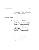
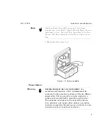
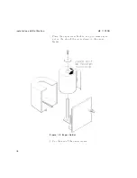
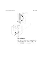
Figure
1-2.
Fuse
assembly
P
o
w
er
Cables
W
arning
BEF
ORE
CONNECTING
THIS
INSTRUMENT,
the
protectiv
e
earth
terminals
of
this
instrument
must
be
connected
to
the
protectiv
e
conductor
of
the
line
(Mains)
po
w
er
cable.
The
line
plug
shall
only
be
inserted
in
a
sock
et
outlet
pro
vided
with
a
protectiv
e
earth
contact.
The
protectiv
e
action
must
not
be
negated
b
y
the
use
of
an
extension
cord
(po
w
er
cable)
without
a
protectiv
e
conductor
(grounding).
Grounding
one
conductor
of
a
tw
o
conductor
outlet
is
not
sufficient
protection.
5

