Honeywell NetAXS User Manual Download Page 85

Configuring via WIN-PAK

Adding a New NetAXS™ Panel

NetAXS™ Access Control Unit User’s Guide

Document 800-00233, Revision A

3

-

11

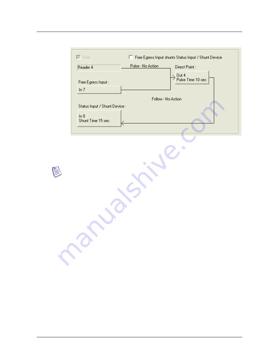
10.The configuration of a NetAXS panel via WIN-PAK is now complete. No 

configuration is necessary on the Outputs and Groups tabs.

Note:  

You cannot initialize the NetAXS panel from the WIN-PAK Control Map.

Summary of Contents for NetAXS

Page 1: ...Honeywell All rights reserved 800 00233 Revision A PRELIMINARY DRAFT 6 1 07 NetAXS Access Control Unit User s Guide The configurations described in this document have not been reviewed by Underwriters Laboratories Inc ...

Page 2: ...y information in this document at any time without prior notice Microsoft and Windows are registered trademarks of Microsoft Corporation Windows Server is a trademark of Microsoft Corporation Ordering Information Please contact your local Honeywell representative or visit us on the web at www honeywellaccess com for information about ordering Feedback Honeywell appreciates your comments about this...

Page 3: ... Tab 2 9 2 2 5 Downstream Devices Tab 2 11 2 2 6 Host Loop Communications Tab 2 12 2 3 Configuring Time Management 2 15 2 3 1 Current Time Tab 2 15 2 3 2 Time Zones Tab 2 17 2 3 3 Holidays Tab 2 19 2 4 Configuring the Doors 2 21 2 4 1 Reader Tab 2 21 2 4 2 Output Tab 2 28 2 4 3 Inputs Tab 2 30 2 5 Configuring Access Levels 2 34 2 6 Maintaining Cards 2 36 2 6 1 Adding New Cards 2 36 2 6 2 Displayin...

Page 4: ...3 1 3 2 Adding a New NetAXS Panel 3 2 3 2 1 Creating the Panel with Quick Start Wizard 3 2 3 2 2 Configuring the Panel Manually 3 3 Chapter 4 Monitoring NetAXS Status 4 1 Overview 4 1 4 2 Monitoring Alarms 4 2 4 3 Monitoring Events 4 5 4 4 Monitoring Inputs 4 7 4 5 Monitoring Outputs 4 10 4 6 Monitoring System Status 4 12 Index ...

Page 5: ...evels 2 34 Figure 2 14 Cards Add Cards 2 36 Figure 2 15 Cards Card Data 2 39 Figure 2 16 Cards Delete Cards 2 40 Figure 2 17 Configuration Other I O Groups Inputs Tab Powerfail 2 43 Figure 2 18 Configuration Other I O Groups Inputs Tab PanelTamper 2 43 Figure 2 19 Configuration Other I O Groups Inputs Tab Downstream 2 44 Figure 2 20 Configuration Other I O Groups Outputs Tab 2 46 Figure 2 21 Confi...

Page 6: ...vi www honeywell com Figure 4 6 Status Outputs Discrete Tab 4 10 Figure 4 7 Status Outputs Groups Tab 4 10 Figure 4 8 Status System 4 12 ...

Page 7: ...le 2 6 Configuration Doors Output Tab Field Descriptions 2 29 Table 2 7 Configuration Doors Inputs Tab Field Descriptions 2 33 Table 2 8 Cards Add Cards Field Descriptions 2 37 Table 2 9 Cards Reports Field Descriptions 2 41 Table 2 10 Configuration Other I O Groups Inputs Tab Field Descriptions 2 45 Table 2 11 Configuration Other I O Groups Outputs Tab Fields 2 48 Table 2 12 Configuration Other I...

Page 8: ...viii www honeywell com ...

Page 9: ... four reader ports See the NetAXS NX4L1 Installation Guide or NetAXS NX4S1 Installation Guide to view illustrations of the supported NetAXS system configurations You access the NetAXS access control unit either through a host software system or by connecting to the NetAXS web server by an Ethernet connection This chapter describes how to connect to the NetAXS web server Chapter 2 describes how to ...

Page 10: ... Perform the following steps 1 Connect your computer s Ethernet port and the NetAXS panel s Ethernet Port by using either of two methods a Connect both the computer s Ethernet port and the NetAXS panels Ethernet port to an Ethernet hub with standard straight through Ethernet patch cables Figure 1 1 NetAXS Web Server Hub Connection b Connect the computer s Ethernet port directly to the NetAXS panel...

Page 11: ...ware Suite Guide Document 7 901071 Revision A 1 3 Figure 1 2 NetAXS Web Server Direct Connection 2 Configure the computer s network connection a Select Start Settings Control Panel b Click Network and Dial up Connections Terminal NetAXS Panel Ethernet Port Ethernet Crossover Cable ...

Page 12: ...ht the Internet Protocol TCP IP connection e Click Properties to display your system s current Internet Protocol properties f Important Keep a record of your computer s current network configuration as it appears in this screen You will need to re instate this configuration later g Select Use the following IP address h Enter 192 168 1 10 in the IP address field i Enter 255 255 255 0 in the Subnet ...

Page 13: ...ng to the NetAXS Web Server Pro Watch Software Suite Guide Document 7 901071 Revision A 1 5 Release 3 7 k Click OK to accept the entries 3 Open your browser Internet Explorer shown below and enter https 192 168 1 150 as the target address ...

Page 14: ...d enter admin in the Password field Both the user name and password are case sensitive 6 Click Login to display the NetAXS main window Note that the Select Panel column on the right edge of the screen displays all panels available to the computer This list will include the gateway panel that you are connected to over Ethernet and any downstream panels connected via RS 485 to the Gateway panel ...

Page 15: ... the NetAXS System Steps to modify a user page 55 1 3 Reading the Select Panel The Select Panel is located at the right margin of the NetAXS web server main screen shown in the preceding section The presence of a number in one of the Select Panel cells indicates that its associated panel is online For example if you see a number 1 in a cell this indicates that panel 1 is online The combinations of...

Page 16: ...ing the Select Panel Cell Display Status Large red number on a blue background such as 1 in the example below Panel 1 is selected and it has unacknowledged alarms Small black number on white background such as 2 in the example below Panel 2 is not selected and it has no unacknowledged alarms Large white number on blue background such as 2 in the example below Panel 2 is selected and it has no unac...

Page 17: ... Software Suite Guide Document 7 901071 Revision A 1 9 Release 3 7 Small white number on a red background such as 1 in the example below Panel 1 is not selected but it does have unacknowledged alarms Table 1 1 Reading the Select Panel continued Cell Display Status ...

Page 18: ...1 10 www honeywell com Connecting to the Web Server Reading the Select Panel ...

Page 19: ...ision A 2 1 2 Configuring via the Web Server Overview 2 2 Configuring the System 2 3 Configuring the Doors 2 21 Configuring Other I O Groups Tab 2 42 Configuring Interlocks 2 51 Configuring Time Management 2 15 Configuring Access Levels 2 34 Configuring Users 2 54 ...

Page 20: ...m Configuration Flow Chart Configure the Panel Configuration System General Network Tab page 8 Configuration System General General Tab page 3 Configuration System Site Codes Site Codes Tab page 9 Configuration System Host Loop Communications Host Loop Communications Tab page 12 Configure the Time Zones Configuration Time Management Time Zones Time Zones Tab page 17 Configure the Access Levels Con...

Page 21: ...General Tab enables you to Set the general configuration settings Reset the panel Steps Use the descriptions in the following table to configure the general settings and click Submit Changes Table 2 1 Configuration System General Tab Fields Parameter Description Name Unique name that identifies the panel Address Displays the address set by the panel s DIP switches Type Displays NetAXS as the panel...

Page 22: ...ul card read at any one of the system s readers Forgiveness Causes all system codes to be reset at midnight every day This enables a cardholder who exited the building in the evening without using his card to use his card for entry the following morning Gateway Panel Addr Sets the panel address of the Gateway panel or the panel directly connected to the host system Web Session Timeout Disabled Dis...

Page 23: ...rrect the door will still open normally but the duress output pulses and an alarm is generated In this way the cardholder notifies others without detection by the unauthorized person Continuous Card Reads Enabled Enables continuous card reading while the output is being energized When this option is not enabled a reader will not be able to read a second card during the pulsing of the output caused...

Page 24: ...ement tab Figure 2 2 Configuration System File Mgmt Tab The File Mgmt tab enables you to View the current firmware configuration Download firmware from the host to the panel Revert to a previous firmware version Upload card and configuration data from the panel to the host system Steps to download firmware from the host to the panel 1 Click Browse to locate the firmware file 2 Click Download to do...

Page 25: ...ss Control Unit User s Guide Document 800 00233 Revision A 2 7 Steps to upload data from the panel to the host 1 Select either Cards Only Configuration Only or All to send card data configuration data or both respectively 2 Click Upload to upload the data to the host ...

Page 26: ...S1 Installation Guide for illustrations of the supported network configurations For the panel to function in any of these configurations the other panels and devices in the network must know the panel s network addresses Click Network to display the Network tab Figure 2 3 Configuration System Network Tab The Network tab enables you to View the panel s MAC address View and edit the panel s IP addre...

Page 27: ...econdary IDs in addition to the card number on the card for additional validation Click Site Codes to display the Site Codes tab Figure 2 4 Configuration System Site Codes Tab The Site Codes tab enables you to View existing site codes Create one or more site codes Modify an existing site code Delete a selected site code Delete all site codes Steps to delete all site codes 1 Click Delete All Codes ...

Page 28: ... Click Add Site Code to create the site code Steps to modify a site code 1 Click the site code s number in the Num column to select the site code 2 Click Modify to display the Name and Site Code fields 3 Modify the name or site code number as you desire and click Modify again Steps to delete a site code 1 In the Num column click the number of the site you want to delete 2 Click Delete to display a...

Page 29: ...and 2 2 16 Provides two inputs and 16 outputs The 2 16 MIRO boards must be assigned network addresses 3 6 Note The MIRO network addresses are set by the DIP switches on each board Refer to the Downstream I O section in the NetAXS Access Control Unit NX4L1 Installation Guide or the NetAXS Access Control Unit NX4S1 Installation Guide for more information about setting MIRO DIP switches A NetAXS pane...

Page 30: ...are system such as WIN PAK connects to the panel through the NetAXS gateway panel which has an on board PCI communications adapter and it enables you to monitor the status of the NetAXS system The on board PCI adapter functions as an interface between a host computer s RS 232 port and one or more panels connected on the Multidrop line Web mode configure and monitor the NetAXS web server connects t...

Page 31: ...ng from a host software system such as WIN PAK select one of the following three connection options Direct via TCP IP Host connects directly to the panel using the TCP IP protocol Direct via RS 232 Host connects directly to the panel via the RS 232 protocol Hub Mode modem Host and the panel both connect to a modem If you will be connecting to the panel through the NetAXS web server click None Comm...

Page 32: ...ed with the host Loop Baud Rate Specifies the transmission rate bits per second among the downstream NetAXS panels on the loop For NetAXS downstream panels it is recommended that you select 115 200 Force Baud Reset Tells all downstream NetAXS panels to change to the selected Downstream baud rate This saves the user from having to go to each panel one by one Table 2 2 Configuration System Host Loop...

Page 33: ... the operation of the inputs outputs groups readers access levels and cards through access levels Defining the holiday schedule 2 3 1 Current Time Tab Click Current Time to display the Current Time screen Figure 2 7 Configuration Time Management Current Time Tab The Current Time tab enables you to Set the current loop time Specify the time format 12 hour 24 hour Set a new date Set a new time Set t...

Page 34: ...d 1 12 24 hour The hours in the 24 hour day are numbered consecutively 0 23 New Date Specifies a new date to be the current date New Time Specifies a new time to be the current time Geographic Time Zone Select the geographic time zone in which the panel will operate Time Server Enter the IP address of the machine whose time is used as the standard for all panels Enabled Select to enable the specif...

Page 35: ... they will be energized or de energized enabled or disabled For example you might assign a group of outputs to be energized from 12 00 a m to 6 00 a m every day The 12 00 a m to 6 00 a m Sunday through Saturday time period is called a time zone The Time Zones tab enables you to create the time zones you will use to configure your NetAXS system Click Time Zones to display the Time Zones screen Figu...

Page 36: ...idays checkbox 5 If the time zone will be linked to another time zone select the linked to time zone s number from the drop down list 6 Click the Add Time Zone button Steps to modify a time zone 1 In the Tz column click the number of the time zone you want to modify 2 Change the time zone settings as you desire 3 Click the Modify button to accept the changes Steps to delete a time zone Caution Do ...

Page 37: ...tab enables you to Create a holiday Modify a holiday Delete a holiday Steps to create a holiday 1 Enter the name of the new holiday in the Name field up to 25 characters 2 If the holiday s duration is one day select Single day If the holiday s duration will be more than one day select Multiple day 3 If the holiday will occur annually select the Annual checkbox 4 Assign a type to the holiday either...

Page 38: ...liday button Steps to modify a holiday 1 In the Holiday column click the number of the holiday you want to modify 2 Change the holiday settings as you desire 3 Click the Modify button to accept the changes Steps to delete a holiday 1 In the Holiday column click the number of the holiday you want to delete 2 Click the Delete button 3 Click OK at the delete prompt ...

Page 39: ... configure the readers inputs and outputs At Configuration Doors in the task menu at the left margin of the NetAXS screen click 1 to display the Door Configuration screen for door 1 Follow the same procedures below for doors 2 3 and 4 for each panel 2 4 1 Reader Tab A reader is a device that reads cards and either grants or denies access at the door Click the Reader tab Figure 2 10 Configuration D...

Page 40: ... be overridden by a card assigned with a VIP card type see Adding New Cards on page 36 for information about assigning a VIP card type Enable the Card Only PIN Only Card and PIN and Card or PIN access modes with either the Supervisor or Escort rule Supervisor Rule When the supervisor presents his card during the specified time zone just once he gains access but does not enable access for non super...

Page 41: ...ered at the door s keypad Card or Pin Grants access with either a successful card read or a valid PIN number entry at the door s keypad Card and Pin Grants access only with both a successful card read and a valid PIN entry at the door s keypad You can perform the card read and PIN entry in either sequence Supervisor Enables a supervisor to enter without allowing access to others When the superviso...

Page 42: ...passback must first be enabled at the Configuration System General screen see General Tab page 3 Enabled Enables the anti passback feature Hard Does not allow a second entry on the same card without an exit Soft Allows a second entry on the same card without an exit however an event is generated that indicates the second entry Out Applies to readers located inside the area Cardholders use these re...

Page 43: ...tion Name Displays the name by which the format will be listed in the Card Formats tab The name is user defined Reverse Bit Order Returns the message from the reader in reverse bit order least significant bit first and most significant bit last Concatenated Site Code Combines the Site Code and Card ID as one unique number Total Num Bits Lists the total number of bits on the card Even Parity Lists ...

Page 44: ... A Lists where on the card the Site Code A is listed Consult the card manufacturer for detail on the card detail Start Bit first bit in the card where the card s Site Code begins Num Bits Number of bits to the right of the start bit including the start bit that comprise the Site Code Most card formats require only Site Code A Site Code B Lists where on the card the Site Code A is listed Consult th...

Page 45: ... click Reset To delete the card format click Delete Site Code D Lists where on the card the Site Code A is listed Consult the card manufacturer for detail on the card detail Start Bit first bit in the card where the card s Site Code begins Num Bits Number of bits to the right of the start bit including the start bit that comprise the Site Code Most card formats require only Site Code A Issue Code ...

Page 46: ...ad at a reader input device causes the output relay switch on the panel board to change the normal state of a door lock output device so that the normally locked door strike releases and permits entry This tab configures the output relays Click the Output tab Figure 2 11 Configuration Doors Output Tab The Output tab enables you to Configure the following for each of the door s output devices Name ...

Page 47: ...sets the period during which the interlock or a programmed interaction between selected inputs and outputs will be disabled Latching When selected this locks a relay either Normally Open or Normally Closed to lock into place until it is reset either manually or by a signal Interlock Enables you to disable the interlock or programmed interaction between this output device and an input device Keep O...

Page 48: ...s has been short circuited Cut supervised input only Reports that the electrical circuit supporting the door has been cut or disconnected Egress Allows the door to open or close normally without generating an alarm Tamper Reports abnormal handling of the reader device or wiring First Card Rule Requires a valid card read before the time zone period in which doors are unlocked can take effect For ex...

Page 49: ... s Guide Document 800 00233 Revision A 2 31 Click to display the Inputs tab Figure 2 12 Configuration Doors Inputs Tab Note that there are four possible Mode configurations Shown in the screen above is the Normally Closed Unsupervised Mode The following screens show the remaining modes ...

Page 50: ... Status Egress and Tamper shunt time or the period of time the door s normal state will be ignored Specify the Status Egress and Tamper debounce time or the period of time the input must remain in its new state before it is recognized as being in the new state Specify the time zones for the Status Egress and Tamper inputs Enable or disable Auto Relock for the Status inputs ...

Page 51: ...r which the inputs will be shunted or de activated For example it specifies how long a door strike will remain released Enter the desired number of hours 1024 maximum minutes 60 maximum and seconds 60 maximum The sum of all three units comprises the shunt time Note that you can express seconds in tenths of a second Time Zones Shunt Specifies the time period during which the input will be ignored D...

Page 52: ... 2 from 6 00 a m to 6 00 p m Monday through Friday This section explains how to create the access levels that subsequently can be assigned to cards Note Since an access level is defined by door and time zone configurations you must configure the door see Configuring the Doors on page 21 and the time zone see Configuring Time Management on page 15 before configuring an access level Click Access Lev...

Page 53: ...t the time zone you want from the drop down list in the Time Zone field The access level will allow access to the card holder only during this time zone 4 Click the Add Level button Steps to modify an access level 1 From the drop down list in the Level field select the number of the access level you want to modify 2 Make the desired modifications 3 Click the Modify button Steps to delete an access...

Page 54: ...example in addition to its unique number a card would allow the card holder to be granted access to certain doors during a certain time of day 2 6 1 Adding New Cards Click Cards Add Card s to display the Add New Card s screen Figure 2 14 Cards Add Cards The Add New Card s screen enables you to Create cards encoded with the following information Card number s Card holder name first and last names C...

Page 55: ...figured for visitor cards in Configuration System General see General Tab on page 3 A card type is required Issue Number Specifies the number of times this card number has been issued to the card holder For example a card holder may lose his original card having an issue number of 1 You would issue him a replacement with the same card number but with an issue number of 2 An issue number is require...

Page 56: ...limited number of days The specified period begins at the time the card is created Limited Use Cards Specifies a card that can be used only a limited number of times Neither Specifies all cards other than visitor or limited use cards If the panel is configured with Visitor Cards limited days the Use Limits field accepts a number of days If the panel is configured with Limited Use Cards the Use Lim...

Page 57: ...ified cards Figure 2 15 Cards Card Data The Display or Modify Card s screen enables you to Display cards by searching on any of the following keys Card number Card holder s last name Modify the displayed card s Steps 1 Enter a value for either of the search keys card number or cardholder last name 2 Click the Display Modify Card s button The cards specified in step 1 appear 3 Use the field descrip...

Page 58: ...e Cards The Delete Card s screen enables you to Delete cards retrieved by any of the following keys Card number Range of card numbers Card holder s last name Steps 1 Enter a value for any of the search keys card number card number range or cardholder name 2 Click Delete Card s to delete all cards matching the search keys you entered 3 Click OK at the prompt to delete the card ...

Page 59: ...orts Field Descriptions Field Description Last Shows the cardholder s last name First Shows the cardholder s first name Card Number Shows the card number Site Shows the Site Code number A Site Code is a user configured name that identifies the site or location of the cardholder s access See Site Codes Tab on page 9 for more information about Site Codes To determine the Site Code name associated wi...

Page 60: ...te inputs that are limited to 2 200 ohms resistance The MIRO 2 16 has two supervised inputs and 16 SPDT relay outputs each input is limited to 2 200 ohms resistance Each board is configured with a unique address in the Configuration System Downstream Devices tab see Downstream Devices Tab on page 11 On panels with internal power supply the Power Fail input generates an alarm when primary power is ...

Page 61: ...Tab NetAXS Access Control Unit User s Guide Document 800 00233 Revision A 2 43 Figure 2 17 Configuration Other I O Groups Inputs Tab Powerfail Click Panel Tamper to display the Panel Tamper screen Figure 2 18 Configuration Other I O Groups Inputs Tab PanelTamper ...

Page 62: ...on Other I O Groups Inputs Tab Downstream The Input tab enables you to Configure the mode debounce time and time zones for the Power Fail input input 13 Configure the mode debounce time and time zones for the Panel Tamper input input 14 Configure the mode shunt time debounce time time zones and auto relock for the downstream inputs provided by downstream MIRO boards ...

Page 63: ...sed Enter the desired number of hours 1024 maximum minutes 60 maximum and seconds 60 maximum The sum of all three units comprises the shunt time Note that you can express seconds in tenths of a second Debounce Time Specifies the period of time the input must remain in a new state before generating an alarm For example if a Normal state is changed to Alarm the state must remain in Alarm for five se...

Page 64: ... outputs 5 8 that are physically located on the panel board and the outputs on downstream 2 16 MIRO boards daisy chained to Terminal Block 10 A NetAXS panel supports a maximum of four 2 16 MIRO boards and each board provides two inputs and 16 outputs The downstream outputs are numbered 17 81 Click Outputs to display the Auxiliary Output screen for the on board outputs Figure 2 20 Configuration Oth...

Page 65: ...2 47 Click Downstream to display the Downstream Output screen Figure 2 21 Configuration Other I O Groups Outputs Tab Downstream The Outputs tab enables you to Configure the following for each of the auxiliary outputs on board the panel as well as downstream Name Pulse time Time zones Latching Interlock Keep on Snow day First card rule ...

Page 66: ...ng which the interlock or a programmed interaction between selected inputs and outputs will be disabled Latching When selected this locks a relay either Normally Open or Normally Closed to lock into place until it is reset either manually or by a signal Interlock Enables you to disable the interlock or programmed interaction between this output device and an input device Keep On Keeps the selected...

Page 67: ...roups to display the Groups screen Figure 2 22 Configuration Other I O Groups Groups Tab First Card Rule Requires a valid card read before the time zone period in which doors are unlocked can take effect For example the principal of a school would normally open the school with a valid card read and the time zone becomes active at its normal time When the school is cancelled due to a storm the prin...

Page 68: ...me Specifies the duration for which the device will assume abnormal status For example it specifies how long a horn will blow or a door strike will remain released Enter the desired number of hours 1024 maximum minutes 60 maximum and seconds 60 maximum The sum of all three units comprises the pulse time Note that you can express seconds in tenths of a second Energized TZ Specifies the period durin...

Page 69: ... specified manner when another input point output point or group of output points changes its state An action on one point cause a reaction from a second point on the same panel or attached MIRO board For example when a motion detector input detects movement it causes a horn output to sound Click Interlocks to display the Interlocks Configuration screen Figure 2 23 Configuration Interlocks The Int...

Page 70: ...on from another input output or group Also use the drop down list to specify the number of the input output or group Reacting Component Specifies the input output or output group that will react to a change of state from the trigger point Also use the drop down list to specify the number of the input output or group Reacting Component s Action Upon Trigger Alarm Specifies the reacting component s ...

Page 71: ...ifications in the empty Trigger Reacting Component and Reacting Component s Action fields for the selected interlock 4 Click the Add Interlock button to complete the modification Steps to delete an interlock 1 In the Int Lk column click the number of the interlock you want to delete 2 Click the Delete Interlock button to display the Delete Interlock screen and click OK to complete the deletion Ste...

Page 72: ...tor Configures the NetAXS system Service Provides diagnostic and support service for the NetAXS system Operator Monitors the system s operation Click Users to display the User Configuration screen Figure 2 24 Configuration Users The User Configuration screen enables you to Create a user Modify a user Delete a user Enable and disable a user account View the user s current login status either logged...

Page 73: ...ed 4 Select the type in the Account Type field 5 Select the Account Status Enabled Activates the user account the user can log in Disabled De activates the user account the user cannot log in 6 Click the Add User button Steps to modify a user 1 In the User Name field click the name of the user you want to modify 2 Change the name password account type or account status 3 Click the Modify button St...

Page 74: ...2 56 www honeywell com Configuring via the Web Server Configuring Users ...

Page 75: ... to WIN PAK PRO Release 4 or older For a new Site installation or for adding to an existing Site follow the procedures in this chapter as you would when you add an N 1000 IV X panel One exception to this is that the NetAXS panel does not support the use of the C 100 A1 20ma current loop installations Therefore when you select the Loop type 485 AC NAK is the only supported type Direct is reserved f...

Page 76: ...ck Start Wizard and then complete the configuration manually with the WIN PAK Panel Configuration screen 3 2 1 Creating the Panel with Quick Start Wizard Add a new panel by selecting its Loop and configuring the following from the Quick Start Wizard Panel screen Panel type Select N1000 4X PW2000 4X from the dropdown list Panel name Loop Loop number Panel Panel address Panel address Select from the...

Page 77: ...figuration except where they are noted otherwise in this section If you are using the Device Map to add the NetAXS panel manually add it as you would an N 1000 IV X panel 1 Display the Basic tab of the WIN PAK Panel Configuration screen The Name Description and Type fields contain the entries selected in the Quick Start Wizard Figure 3 2 WIN PAK Panel Configuration Screen Basic Tab 2 Enter the fol...

Page 78: ...3 4 www honeywell com Configuring via WIN PAK Adding a New NetAXS Panel 3 Click OK 4 Display and complete the Card Format tab Figure 3 3 WIN PAK Panel Configuration Screen Card Format Tab ...

Page 79: ...anel NetAXS Access Control Unit User s Guide Document 800 00233 Revision A 3 5 5 Display and complete the Time Zones tab Figure 3 4 WIN PAK Panel Configuration Screen Time Zones Tab Note All Time Zones and Holidays are supported for a NetAXS panel ...

Page 80: ... except the Advanced U option When using Groups you must select both AEP boards in the Hardware Options box The NX4OUT board functions as two AEP 3 boards and it provides outputs 17 32 You can select Keypads however the NetAXS panel does not support the matrixed keypads for example KP 10 KP 12 or PR PROXPRO K2 The supported readers include the PR PROXPRO K HU 5355AGK000 and OT35xx and OT36xx serie...

Page 81: ...vate a request to exit then you must reassign the interlocks as indicated below If you are not using panel inputs for door status or egress you only need to dissolve the interlocks Note that if you do not dissolve the default N 1000 IV interlocks an error will occur during NetAXS panel initializations All Inputs tab functions are available to NetAXS configuration However not all inputs are availab...

Page 82: ...input for each reader on this tab c After all interlocks on all inputs for each reader have been dissolved reassign the interlocks according to Table 3 1 below Table 3 1 Interlock Reassignments for NetAXSs Interlock Function 1 Door egress for Door 1 2 Door status switch for Door 1 Shunt time is 15 seconds 3 Door egress for Door 2 4 Door status switch for Door 2 Shunt time is 15 seconds 5 Door egre...

Page 83: ...onfiguration for the default interlocking for a single door 11 Reader 3 tamper auxiliary 12 Reader 4 tamper auxiliary 13 Primary power status external or General input There is also a system primary power alarm 17 that reports through the ADV and is not a wired port 14 Tamper or General input Table 3 1 Interlock Reassignments for NetAXSs continued Interlock Function ...

Page 84: ...3 10 www honeywell com Configuring via WIN PAK Adding a New NetAXS Panel ...

Page 85: ...s Control Unit User s Guide Document 800 00233 Revision A 3 11 10 The configuration of a NetAXS panel via WIN PAK is now complete No configuration is necessary on the Outputs and Groups tabs Note You cannot initialize the NetAXS panel from the WIN PAK Control Map ...

Page 86: ...3 12 www honeywell com Configuring via WIN PAK Adding a New NetAXS Panel ...

Page 87: ...ecorded transactions of the NetAXS system For example an event card found number of users logged in Inputs Inputs are terminals located on the NetAXS panel the inputs are wired to input points such as a card reader elsewhere in the NetAXS system Outputs Output relays are switches located on the NetAXS panel that are connected to output devices such as a door lock elsewhere in the NetAXS system Sys...

Page 88: ...d as system generated messages that may indicate the need for user attention Note From the drop down menu at the upper right corner of each Alarms tab you can configure the tab to display alarms in groups of 10 25 50 or 75 Click Status Alarms to display the New Alarms tab Figure 4 1 Status Alarms New Tab ...

Page 89: ... only Enables you to select any or all of the alarms that you want to acknowledge Note that acknowledging an alarm simply means that you acknowledge that the alarm exists an acknowledgement does not mean action has been taken To acknowledge an alarm select the check box and click the Acknowledge Selected Alarms button Note that you can select or de select all of the alarms by selecting or de selec...

Page 90: ...ce when the device was configured in Configuration Doors PN Physical device number the unique number assigned to the device on the NetAXS board Code Identifies the current state of the device that generated the alarm For example the possible states could include Normal State Alarm State Ajar State Card Found Card Not Found Credential Identifies the card number Card Holder Name Identifies the last ...

Page 91: ...display the Panel event tab Figure 4 3 Status Events Panel Tab The following table describes the information displayed on the Panel events tab Table 4 2 Status Events Panel Tab Field Descriptions Column Head Description Date Time ID Provides the date and exact time the event was generated according to the panel s name Device Name ID Identifies the device that generated the event LN Logical device ...

Page 92: ... tab or display the newest events first by clicking Newest Click Older to scroll through the list by displaying the next oldest tab display of events PN Physical device number the unique number assigned to the device on the NetAXS board Code Briefly describes the event Credential Identifies the card number Card Holder Name Identifies the last name of the card holder who energized the input device ...

Page 93: ...lay the Input Status screen Figure 4 5 Status Inputs The Input Status screen enables you to View the current status of each input Normal Alarm Trouble Cut Short Shunted Shunt or un shunt any input When an input is shunted the alarm is de activated This is a way you can allow the input to grant access without falsely signalling an alarm The default state of an input point is un shunted Restore the ...

Page 94: ...4 8 www honeywell com Monitoring NetAXS Status Monitoring Inputs Steps 1 To shunt or un shunt an input click the input name to display a prompt Click OK to complete the shunt or un shunt ...

Page 95: ...rol Unit User s Guide Document 800 00233 Revision A 4 9 2 To restore the input to its shunt state based on its configured time zone click the input s Restore to Time Zone button to display a prompt Click OK to complete the restoration to the configured time zone ...

Page 96: ...h of its four doors The panel also supports four additional outputs for auxiliary devices and 64 downstream outputs Outputs can be configured singly as discrete outputs see Output Tab on page 28 and Outputs Tab on page 46 or collectively as a group of outputs Groups Tab on page 49 Note The Pulse and Restore to Time Zone buttons will be greyed out if no outputs are attached Click Status Outputs to ...

Page 97: ...nt on page 15 Steps 1 To energize an output or group of outputs for an indefinite period of time click the De energized button to display a prompt Click OK to complete the change to Energized To de energize an output or group of outputs for an indefinite period of time click the Energized button to display a prompt Click OK to complete the change to De energized 2 To Pulse an output or group of ou...

Page 98: ...stem other than alarms events inputs and outputs Click Status System to display the System Status screen Figure 4 8 Status System The System Status screen enables you to View the following status of system objects other than alarms events inputs and outputs Number of currently configured instances of the object Maximum number of object instances that can be configured ...

Page 99: ...Monitoring NetAXS Status Monitoring System Status NetAXS Access Control Unit User s Guide Document 800 00233 Revision A 4 13 ...

Page 100: ...4 14 www honeywell com Monitoring NetAXS Status Monitoring System Status ...

Page 101: ...4 adding 2 36 card formats 2 24 card type 2 37 cardholder notes 2 4 2 5 deleting 2 40 displaying 2 39 issue number 2 37 limited use 2 5 modifying 2 39 PIN 2 37 reports 2 41 site code 2 9 2 37 trace 2 37 use limits 2 38 use types 2 5 visitor 2 5 Communications host baud rate 2 13 loop baud rate 2 14 port number 2 14 type 2 13 Configuration database 2 6 Configuration flow chart 2 2 Configuration mod...

Page 102: ...Host connection 2 13 Host mode monitoring 2 12 I Inputs 2 30 4 1 AC Power Fail 2 42 auto relock 2 33 2 45 debounce time 2 45 downstream 2 42 for WIN PAK configuration 3 7 interlocks 2 51 3 7 MIRO boards 2 42 mode 2 31 2 33 2 45 monitoring 4 7 Panel Tamper 2 42 readers 2 21 3 7 shunt time 2 33 2 45 shunting 4 8 time zones 2 33 2 45 Interlocks 2 29 2 48 2 51 for WIN PAK configuration 3 7 IP address ...

Page 103: ... 1 7 Panels addresses 2 4 configuring via WIN PAK 3 2 downstream baud rate 2 14 gateway 2 4 reboot 2 4 reset 2 4 setting current time 2 15 Personal Identification Number see PIN 2 4 PIN 2 4 2 37 Port number 2 14 Pulse time 2 29 2 48 Q Quick Start Wizard 3 2 R R1 2 33 R2 2 33 Readers 2 21 access mode 2 23 anti passback 2 24 card formats 2 24 LEDs 2 5 tamper 2 30 Reports 2 41 Resistor values 2 33 S ...

Page 104: ...2 33 2 34 2 45 2 48 4 11 for WIN PAK configuration 3 5 Timeout 2 4 Trace 2 37 Trigger 2 52 U Unsupervised 2 32 2 33 Uploading card and configuration data 2 6 Use limits 2 38 Users 2 54 V Visitor cards 2 5 W Web mode monitoring and configuring 2 12 Web server 1 1 Web server connection 1 2 direct 1 3 hub 1 2 Web session timeout 2 4 ...

Page 105: ...ems 135 W Forest Hill Avenue Oak Creek WI 53154 United States 800 323 4576 414 766 1798 Fax www honeywellaccess com Specifications subject to change without notice Honeywell All rights reserved Document 800 00233 Revision A ...

Reviews: