background image

• Recording :

• Spot Monitor 1 to 4 :

• Hold Time :

• Next > :

• Exit :

This allows you to select how video will record during an

alarm condition. INT interleaves images from the camera with an

alarm every other field giving you more images from that camera.

When there are multiple alarms, the cameras with alarms are

interleaved.

ONLY records images from only the camera with an alarm condition.

UNC leaves the recording parameters unchanged.

When set to On, that Spot Monitor will display

the camera with an alarm condition. When there are multiple alarms,

cameras with alarms will display sequentially. When set to Off, that

Spot Monitor’s display does not change during alarm conditions.

This allows the user to set the alarm actions to last from

1 to 99 seconds. Hold Time is applicable only if the alarm action is set

to Timed OUT.

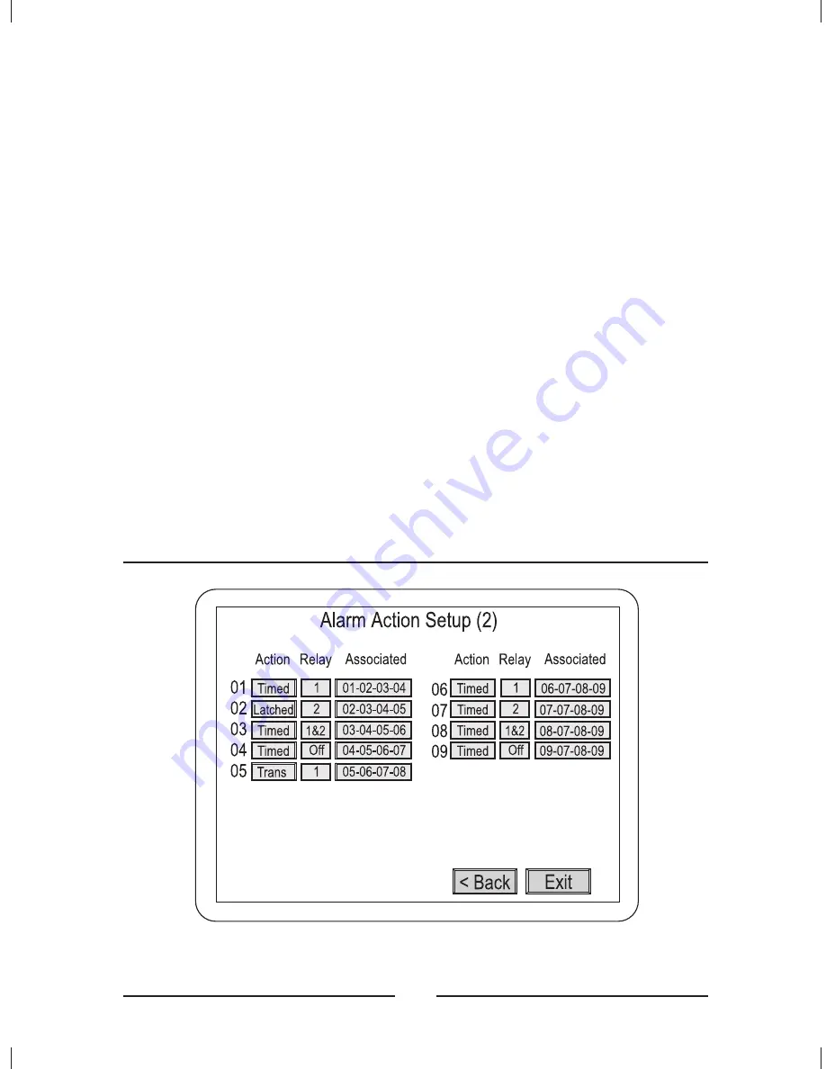
This takes you to the Alarm Action Setup (2) submenu.

Saves your changes and returns to the Main Menu.

Alarm Action Setup (2)

< Figure 16 >

Alarm Action Setup (2) screen.

20

Summary of Contents for HXMT9

Page 1: ...Installation Manual 9 Channel Black White Multiplexer HXMT9 HXMT9X ...

Page 2: ......

Page 3: ...NSIDE REFER SERVICINGTO QUALIFIED SERVICE PERSONNEL The lightning flash with arrowhead symbol within an equilateral triangle is intended to alert the user to the presence of uninsulated dangerous voltage within the product s enclosure that may be of sufficient magnitude to constitute a risk of electric shock to persons The exclamation point within an equilateral triangle is intended to alert the u...

Page 4: ...ays or more To disconnect the cord pull it out by the plug Never pull the cord itself Allow adequate air circulation to prevent internal heat build up Do not place the unit on soft surfaces rugs carpets sofas etc or near materials curtains draperies that may block the ventilation holes Height and vertical linearity controls located on the rear panel are for special adjustments by qualified personn...

Page 5: ...le operation of the video equipment and to protect it from overheating These openings must not be blocked or covered The openings should never be blocked by placing the unit on a bed sofa rug or other similar surface The unit should never be placed near or over a radiator or heat register The unit should not be placed in a built in installation such as a bookcase unless proper ventilation is provi...

Page 6: ...g the unit and equipment from the wall outlet and refer servicing to qualified service personnel under the following conditions A When the power supply cord or the plug has been damaged B If liquid has spilled or objects have fallen into the unit C If the unit has been exposed to rain or water D If the unit does not operate normally when following the operating instructions adjust only those contr...

Page 7: ...RATION OF THIS EQUIPMENT IN A RESIDENTIAL AREA IS LIKELY TO CAUSE HARMFUL INTERFERENCE IN WHICH CASE THE USER WILLBE REQUIRED TO CORRECTTHE INTERFERENCE AT HIS OWN EXPENSE FCC COMPLIANCE STATEMENT CAUTION CHANGES OR MODIFICATIONS NOT EXPRESSLY APPROVED BY THE PARTY RESPONSIBLE FOR COMPLIANCE COULD VOID THE USER S AUTHORITY TO OPERATE THE EQUIPMENT WARNING THIS IS A CLASS A PRODUCT IN A DOMESTIC EN...

Page 8: ...ctions 8 Initial Setup 8 Accessing the Main Menu 8 Main Menu Settings 10 Time Date Setup 11 Camera Access Setup 13 Camera Title Setup 14 Camera Sequence Setup 15 Alarm Setup 16 Alarm I O Setup 18 Alarm Action Setup 1 19 Alarm Action Setup 2 20 Associated Camera Setup 22 Motion Action Setup 1 23 Motion Action Setup 2 24 Video Loss Action Setup 25 Manual Alarm Action Setup 1 27 Manual Alarm Action S...

Page 9: ...CR System Setup 41 Recording Index Setup 42 Camera Picture Adjustment 43 Macro Setup 45 Macro Record Setup 46 Macro Schedule Setup 47 Unit Setup 48 Password Setup 50 Assigning Passwords 51 53 Buttons and Their Functions 53 Menu Operation 56 Top Menu 56 Bottom Menu 56 Live Screen 57 Pop Up Menu 58 Live Camera Change 59 VCR Camera Change 60 Zoom 61 Full 62 Priority On 62 Histogram Equalizer 62 Panic...

Page 10: ...xers 74 Remote Command Set 75 Functional remote commands 76 77 Operating Defaults 77 Factory Defaults 77 Video Format 80 Video Level 80 Main Output Display Formats live and playback 80 Resolution pixels x lines 80 Sampling Standard 81 Video Memory 81 Refresh Rate fields sec 81 Display Options 81 Motion Detection 82 VCR Playback 82 Appendix A Troubleshooting Appendix B Connector Pin Outs Appendix C...

Page 11: ...lay Spot 83 Other Features Internal 83 Other Features External Interface 84 Remote Control 84 Rear Panel Connectors 84 Front Panel Controls 85 Power Requirements 85 Power Adapter 85 Dimensions 86 Weight 86 Operating Environment 86 xi ENGLISH ...

Page 12: ...tup 2 screen 20 Figure 17 Associated Camera Setup submenu 22 Figure 18 Motion Action Setup 1 screen 23 Figure 19 Motion Action Setup 2 screen 24 Figure 20 Video Loss Action Setup screen 25 Figure 21 Manual Alarm Action Setup 1 screen 27 Figure 22 Manual Alarm Action Setup 2 screen 29 Figure 23 Macro Link Setup screen 30 Figure 24 Alarm History List screen 31 Figure 25 Motion Detection Setup screen...

Page 13: ...6 Figure 46 3x3 Live Screen 57 Figure 47 Pop Up menu 58 Figure 48 Live Cam Change menu 59 Figure 49 VCR Cam Change menu 60 Figure 50 Zoom Screen 61 Figure 51 Histogram Equalizer menu bar 62 Figure 52 Sequence menu 63 Figure 53 Utilities Pop Up menu 64 Figure 54 User Screen Change menu bar 64 Figure 55 Select a Screen menu 65 Figure 56 OSD Setup screen 66 Figure 57 Spot output change screen 68 Figu...

Page 14: ...xiv ...

Page 15: ...eras can be assigned to any display format Multiple monitor outputs 1 Main 4 Auxiliary allow simultaneous multi camera and full screen viewing Multilingual setup menus include English French Italian German Polish and Spanish On screen display includes date time alarm status video loss camera number and 24 character camera titles Programmable day and night motion detection schedules Figure 1 Typica...

Page 16: ...inst power outages One TTL CMOS contact closure alarm for each camera Up to 4 cameras can be associated with a single contact closure alarm Alarm input polarity is user selectable VCR switch pulse input for synchronization with VCRs having switch pulse feature Full triplex operation allows simultaneous recording playback and live viewing 256 event alarm history log Linear Zoom in and out up to 32 ...

Page 17: ...an be used for spot monitors or as sources of video for other devices The has a large selection of user selectable display formats It also has digital zooming from 1 to 32 times The multilingual menu options allow for easy setup The user s configuration is stored in nonvolatile memory so that it will not be lost during power outages The can play back videotapes recorded with many other multiplexer...

Page 18: ...4 ...

Page 19: ...ng Cameras You can connect up to 9 cameras to the Connect the camera BNCs to the IN BNC connectors top row The loop through connectors OUT are auto terminated so terminating resisters are not needed if you do not loop video out to another device multiplexer NOTE Connecting a cable to the loop through connector switches off the termination Do NOT connect a cable to the loop through BNC connectors u...

Page 20: ... multiplexer You can use these as spot monitors or to view live video while playing tapes back through the main monitor The auxiliary monitors should be connected to the AUX BNC connectors Connecting Monitors There are BNC connectors for the VCRs Connecting VCRs Figure 3 Connecting one VCR to the multiplexer 6 ...

Page 21: ...ther multiplexer to your system connect the RS 485 OUT connector of the additional unit to the IN RS 485 connector See Setup Menu section to set multiplexer address The remote keyboard should be connected to the OUT connector on the multiplexer multiplexer The multiplexer menus can be controlled by either buttons on the front panel or by a mouse If you plan to use a mouse connect it to the mini DI...

Page 22: ...d hold the and M buttons 3 Turn on the power To set up the multiplexer for CCIR operation 1 Turn off the power 2 Press and hold the and buttons 3 Turn on the power NOTE When changing the multiplexer to EIA or CCIR all other settings are returned to the factory defaults 8 Accessing the Main Menu NOTE To access the Main Menu you must have a Supervisor Password The last item of the Main Menu is the P...

Page 23: ... the circles beside Supervisor Password fill in and move to the right Once you have entered all four digits click on OK If you have entered the correct four digit number the Main Menu will appear If you have entered an incorrect number Incorrect Password displays for ten seconds and then the unit returns to a live display The factory default passwords are listed in the Technical Specifications Cli...

Page 24: ...Main Menu Settings Figure 7 Main Menu screen Figure 8 Time Date Setup first screen 10 ...

Page 25: ... hour formats to choose from One is 24 hour military time The second is AM PM There are two choices for the clock source If your multiplexer is connected to a network set the option to Network Clock and the unit will receive the clock information from the master multiplexer If your multiplexer is not connected to a network set the option to Internal Clock Use the arrow or mouse buttons to change t...

Page 26: ...times Set the Month and Date that your area begins Daylight Saving time Unless there is an unusual situation you will not need to set From and To times Set the Month and Date that your area ends Daylight Saving time Unless there is there is an unusual situation you will not need to set From and To times Selecting this takes you back to the first Time Date Setup Screen Selecting this saves your set...

Page 27: ...s to and which cameras can be displayed on the Spot auxiliary monitors You can also designate whether a camera can be recorded Goes to Camera 1 Goes back one camera Goes forward one camera Goes to Camera 9 An next to an item activates the camera for that output An deactivates the camera Saves your changes and returns to the Main Menu O Exit O 13 ENGLISH ...

Page 28: ...rs enters them in the camera title Each camera title can have a maximum of 24 characters Moves the cursor left Moves the cursor right Goes to Camera 1 Goes back one camera Goes forward one camera Goes to Camera 9 Changes the keyboard characters to the previous set Changes the keyboard characters to the next set Top Top Middle Middle Middle Middle Bottom Bottom 14 ...

Page 29: ... Ô Ö Ù Ú Û Ü ß à á â Saves your changes and returns to the Main Menu BLANK 0 to 9 ä ç è é ê ë ì í î ï ñ ò ó ô ö ù ú û ü Keyboard Character Set 6 Camera Sequence Setup Figure 12 Camera Sequence Setup screen This screen allows you to set the order in which the cameras appear when the multiplexer is in sequence mode You can also set the how long each camera will display from Off to 99 seconds 15 ENGL...

Page 30: ...13 Alarm Setup screen The Alarm Setup screen allows you to enter six alarm submenus Setting this to On allows users to clear alarm events using the front panel buttons or the Pop Up menu Setting it to Off requires the user to enter the Setup Menus to clear alarm events This sets the display mode the multiplexer will use when an alarm occurs There are four possible settings Full 2x2 2x2 Associated ...

Page 31: ... Action Setup Video Loss Action Setup Manual Alarm Action Setup Macro Link Setup Exit Enters the Alarm I O Setup submenu Enters the Alarm Action Setup submenu Enters the Motion Action Setup submenu Enters the Video Loss Action submenu Enters the Manual Alarm Action Setup submenu Enters the Macro Link Setup submenu Saves your changes and returns to the Main Menu 17 ENGLISH ...

Page 32: ...een You can set the input and output for each of the alarm connections Can be set to NO Normally Open NC Normally Closed or Off Can be set to AH Active High or AL Active Low TTL output Saves your changes and returns to the Main Menu In Out Exit 18 ...

Page 33: ...m condition When set to On the screen display will change to the one defined in the Alarm Screen Format menu during an alarm condition When set to On the multiplexer sends the alarm information to an external relay box via the network during an alarm condition When set to On an A displays on the screen when an alarm condition occurs It remains on the screen until it is cleared Buzzer Alarm Screen ...

Page 34: ...s the recording parameters unchanged When set to On that Spot Monitor will display the camera with an alarm condition When there are multiple alarms cameras with alarms will display sequentially When set to Off that Spot Monitor s display does not change during alarm conditions This allows the user to set the alarm actions to last from 1 to 99 seconds Hold Time is applicable only if the alarm acti...

Page 35: ...ns Transparent The alarms are not latched and cannot be cleared by the operator There are four possible relay settings 1 or 2 Sets either internal relay 1 or 2 to be activated by an alarm 1 2 Sets both internal relays 1 and 2 to be activated by an alarm Off Neither internal relay will be activated by an alarm This button allows you to associate other cameras with a camera that is in an alarm condi...

Page 36: ...ameras shown below Under each of the associated camera windows is a control bar Goes through the cameras in reverse order By setting this to On the selected camera will be associated with the camera with the alarm condition If all three Associated Cameras are set to Off no cameras will be associated to the camera with that camera Goes through the cameras in forward order Saves your changes and ret...

Page 37: ...condition When set to On the screen display will change to the one defined in the Alarm Screen Format menu during a motion alarm condition When set to On the multiplexer sends the alarm information to an external relay box via the network during a motion alarm condition When set to On an M displays on the screen when a motion alarm condition occurs It remains on the screen until it is cleared Buzz...

Page 38: ...ages from only the camera with an alarm condition UNC leaves the recording parameters unchanged When set to On that Spot Monitor will display the camera with a motion alarm condition When there are multiple alarms cameras with alarms will display sequentially When set to Off that Spot Monitor s display does not change during motion alarm conditions This takes you to the Motion Alarm Action Setup 2...

Page 39: ...will be activated by a motion alarm This button links the motion detection to an alarm action It can be set to Off or any one of the 9 alarm actions All alarm actions take priority over motion actions This takes you to the Motion Alarm Action Setup 1 submenu Saves your changes and returns to the Main Menu Relay Alarm Link Back Exit Video Loss Action Setup Figure 20 Video Loss Action Setup screen T...

Page 40: ...Off means neither relay will activate When set to On the multiplexer sends the video loss information to an external relay box via the network during a video loss condition When set to On a V displays on the screen when a video loss condition occurs It remains on the screen until it is cleared When set to On that Spot Monitor will display the camera with a video loss condition When there are multi...

Page 41: ...alarm condition When set to On the screen display will change to the one defined in the Alarm Screen Format menu during a Manual alarm condition When set to On the multiplexer sends the alarm information to an external relay box via the network during a Manual alarm condition When set to On an A displays on the screen when a Manual alarm condition occurs It remains on the screen until it is cleare...

Page 42: ...ondition UNC leaves the recording parameters unchanged When set to On that Spot Monitor will display the camera with a Manual alarm condition When there are multiple alarms cameras with alarms will display sequentially When set to Off that Spot Monitor s display does not change during Manual alarm conditions This allows the user to set the alarm actions to last from 1 to 99 seconds Hold Time is ap...

Page 43: ...rm remains active until the operator acknowledges it Trans Transparent The alarms are not latched and cannot be cleared by the operator There are four possible relay settings 1 or 2 Sets either internal relay 1 or 2 to be activated by an alarm 1 2 Sets both internal relays 1 and 2 to be activated by an alarm Off Neither internal relay will be activated by an alarm Action Relay Alarm Link This sele...

Page 44: ...ves your changes and returns to the previous menu Macro Link Setup Figure 23 Macro Link Setup screen This screen allows you to link macros to the 9 alarms Each alarm can be set to Off or linked to any of 9 macros Saves your changes and returns to the previous menu Exit 30 ...

Page 45: ...ne page in the history list Goes to the last page in the history list maximum 16 pages This clears all the information from the history list You will be asked to confirm that you really want to delete all the alarm history information before it is deleted Clear multiplexer Transmits all alarm history list to PC Print NOTE Before implement Print function make sure follow the below steps 1 Go to the...

Page 46: ... to that submenu Takes you to that submenu Takes you to that submenu Saves your changes and returns to the Main Menu All Motion Detection Motion Detection Index Setup Motion Detection Schedule Setup Motion Detection Sensor Setup Exit 32 2 Download the Download exe file on your PC 3 Implement the Download exe file and click the icon named Print Program 4 Now user s are ready to use Print function E...

Page 47: ...ases the camera number by one Decreases the camera number by one Scrolls through the camera array to the left Scrolls through the camera array to the right Deletes the highlighted camera from the array Inserts a blank into the array Enters an E which sets the end mark for the index list Displays the Motion Detection Index List Saves your changes and returns to the previous menu Delete Insert End V...

Page 48: ...on Detection Index List Figure 27 Motion Detection Index List screen This screen displays the priorities assigned to the cameras You cannot edit anything on this screen Returns to the previous menu Exit 34 ...

Page 49: ...nerate an alarm condition Each timer can be turned On or Off and they can be set to Mode 1 or 2 Modes 1 and 2 are defined in the Motion Detection Sensor Setup screen You can set the start and stop time for each timer A start time of 18 00 with an end time of 06 00 will go from 6 00 p m until 6 00 a m of the following morning The timers can be turned On or Off for each day of the week On and Off Sa...

Page 50: ...On or Off When using Update the multiplexer compares the current field with the previous one When using Master the multiplexer compares a master image to continuous video When set to Normal the multiplexer detects all motion When set to Vector the multiplexer detects motion based on user definitions Sets how much luminance change there must be in the target area before the multiplexer reads the ch...

Page 51: ...s motion The range is 01 to 16 The delay time is used to make adjustments for scenes that have sudden changes such as lights and shadows created by headlights of nearby traffic The delay can be set from 0 to 5 seconds The Hold Time can be set from 1 to 99 seconds Takes you to the Motion Detection Sensor Setup screen Goes to Camera 1 Goes back one camera Goes forward one camera Goes to Camera 9 Sav...

Page 52: ...or Vector motion detection The following describes Normal motion detection Highlights the grids area Click of the mouse on this icon has no action SET Dot Line All Reverse Test Exit Determines how many targets will be turned on or off Dot single target Line a row of targets All all the targets Set all targets to the reverse side Goes to the Motion Detection Sensor Setup test screen Saves your chan...

Page 53: ...hen the multiplexer detects motion by drawing a box around the active area This gives you instant feedback letting you know if you have set the correct size and sensitivity for the types of motion you want to detect Saves the master image This button only appears in the Master Mode Returns to the previous menu Master Screen Set Exit 39 ENGLISH ...

Page 54: ...grid and then define a second grid to the right of the first Used to define the first grid Used to define the second grid Refer to Motion Detection Sensor Setup Normal for descriptions of all the other settings A ON B ON Playback Recording Setup The Playback Recording Setup screen gives you access to submenus for setting up playback and recording Opens the submenu Opens the submenu Saves your chan...

Page 55: ...nchronizing trigger pulse set to match the VCR s signal for positive edge sensing and for negative edge sensing When On the buzzer will beep every 20 seconds Selecting this brings up a list of VCRs Select your VCR from the list If your VCR is not on the list select User Define NOTE If your VCR has a synchronizing trigger pulse using it will save you a lot of time when setting up your system VCR In...

Page 56: ...e lapse and Alarm to 2 hour mode You will need to get the field delay rates from your VCR manufacturer Saves your changes and returns to the previous menu Figure 34 Recording Index Setup screen Recording Index Setup Normally the multiplexer gives the same priority to all cameras However you can set it up so that cameras are given different recording priorities Increases the camera number by one De...

Page 57: ...splays the Motion Detection Index List Saves your changes and returns to the previous menu Figure 35 Camera Picture Adjustment screen Camera Picture Adjustment NOTE Do not make any adjustments with this screen until all of the cameras and monitors have been adjusted properly Goes to Camera 1 Goes back one camera Goes forward one camera Goes to Camera 9 43 ENGLISH ...

Page 58: ...e other values are Min minimum 127 to 01 adjustments below default 01 to 127 adjustments above default and Max maximum Adjusts contrast Adjusts brightness Saves your changes and returns to the Main Menu Contrast Brightness Exit Sharpness Adjusts sharpness 44 ...

Page 59: ...reen Macro Setup The Macro Setup screen lets you access the two macro setup submenus Opens the submenu Opens the submenu Saves your changes and returns to the Main Menu Macro Recording Setup Macro Schedule Setup Exit 45 ENGLISH ...

Page 60: ...etup Selecting any of the Record Start buttons takes you to a live screen where all of your key strokes or mouse operations except for password protected operations will be recorded as a macro Saves your changes and returns to the previous menu Exit 46 ...

Page 61: ... Figure 38 Live screen with M01 REC on the screen Figure 39 Macro Schedule Setup screen Macro Schedule Setup 47 ENGLISH ...

Page 62: ...me the event is to be done Sets the day s the event is to be done enables the event disables the event Saves your changes and returns to the previous menu Event On Off Macro Time Day O Exit Figure 40 Unit Setup screen Unit Setup This screen allows you to change the basic settings There are five languages available English French Italian German Polish and Spanish Language multiplexer 48 ...

Page 63: ...2 will have Cameras 10 to 18 etc When set to Off the cameras will be numbered 01 to 9 When installed as part of a network this will determine if the unit is a master or slave unit The can be set to RS 232 RS 422 or RS 485 when connected to a network When connected to a network the baud rate can be set to 1200 2400 4800 9600 or 19200 Networked multiplexers can be assigned addresses from 001 to 255 ...

Page 64: ... Setup screen allows you to assign PIN codes to the supervisor and up to four users When On only the supervisor can enter and make changes in the Setup Menu When On a password will be required to make screen configuration changes or to access items on the Pop Up menu Opens the Password Entry screen Opens the Password Entry screen Saves your changes and returns to the Main Menu Setup Menu Password ...

Page 65: ...er a four digit PIN Deletes all entered numbers and you can restart entry Opens the re enter screen after the first try Compares the entry to the first password and exits the Setup Menu if they match Cancels the password setup and exits the Setup Menu Clear OK Cancel 51 ENGLISH ...

Page 66: ...52 ...

Page 67: ...r VCR preview mode Press to switch the multiplexer into VCR playback mode Press 2nd and then to switch the VCR to preview mode Plays a Macro Press and then a camera button to play macros 1 to 9 Puts a camera in the Panic Record Mode Press and then a camera button to put that camera in the panic record mode Puts the multiplexer in Full Screen Mode or the first user defined display mode OPERATION OP...

Page 68: ...o display the second screen layout previously defined by the user Puts the multiplexer in PIP4 display mode or the third user defined display mode Press and five cameras display on the screen Press and then to display the third screen layout previously defined by the user Puts the multiplexer in 3x3 display mode or the fourth user defined display mode Press and nine cameras display on the screen P...

Page 69: ...is button has several functions it brings up a Popup Menu sets selections on the OSD menus and decreases numbers in the number setup function Press to enter the Popup Menu or to set a selected item from on of the menus This button has several functions it acts as a Cancel button clears Cameo selections and increases numbers in the number setup function Press to cancel entries clear the Cameo or to...

Page 70: ...edge of the screen Top Menu Figure 44 Top Menu The Top Menu has five selections Clicking on Live returns to the last Live mode screen format displayed Clicking on Playback returns to the last screen format accessed in the Playback mode Clicking on Preview displays the Preview mode Clicking on Setup opens the Setup Menu This feature is password protected See Chapter 2 for a description of the Setup...

Page 71: ...splayed on the screen User Def1 to 4 Switch to user defined displays 1 to 4 Cancel Exits the menu without any changes PIP4 Switches to five cameras displayed on the screen Live Screen Figure 46 3x3 Live Screen When you move the mouse around while in the live screen mode or when you press the Up Down Left and Right arrow buttons the boarder around the selected camera image will change to white This...

Page 72: ...Up menu Allows you to select the Live camera Enters the digital zoom mode Displays the selected camera full screen Toggles between On and Off Toggles between On and Off Toggles between On and Off Toggles between On and Off Enters the Sequence setup mode Enters the Utilities mode Closes the menu Live Cam Change Zoom Full Priority Histogram Panic Record Freeze Sequence Utilities Cancel 58 ...

Page 73: ...am Change menu Live Camera Change The Live Camera Change menu allows you to assign any camera to active cameo Selecting these buttons changes the cameo camera Exits the menu without any changes 1 to 9 Cancel 59 ENGLISH ...

Page 74: ...his menu will appear on the Pop Up menu only when the unit is Playback mode The VCR Camera Change menu allows you to assign any camera to active cameo to Selecting these buttons changes the cameo camera Exits the menu without any changes 1 9 Cancel 60 ...

Page 75: ...icture insert at the bottom right shows the entire seen with a rectangle representing the zoomed area Clicking this freezes the image on the screen Zooms in enlarges Zooms out The arrow buttons are used to move the zoomed area left right up and down Clicking this button exits the Zoom Mode Freeze In Out Arrow buttons Exit 61 ENGLISH ...

Page 76: ...e refresh rate of the other cameras will slow down Figure 51 Histogram Equalizer menu bar HEQ1 to 4 Each Histogram Equalizer button increases image contrast HEQ1 has the weakest equalization and HEQ4 has the strongest equalization NOTE Image noise increases as you use stronger equalization This is a property of the equalization algorithm and is does not indicate a problem with your system 62 ...

Page 77: ...al value Cancel exits the menu without any changes Panic Record On When Panic Record is selected only the selected camera is recorded and it records in real time speed Freeze On When Freeze is selected the image is frozen on the screen until you reset it Sequence Figure 52 Sequence menu 63 ENGLISH ...

Page 78: ... that are not currently displayed on the screen This selection starts a sequence that was defined in the Setup Menu Exits the menu without any changes Turn All Cam Seq On Turn User Set Seq On Cancel Utilities Figure 53 Utilities Pop Up menu User Scrn Chg Figure 54 User Screen Change menu bar 64 ...

Page 79: ...the Select a Screen menu appears OK Cancel Jumps back through the first screen formats at a time Scrolls back through the screen formats one at a time Scrolls forward through the screen formats one at a time Jumps forward through the last screen formats at a time Confirms the screen format selection Exits the menu without any changes Figure 55 Select a Screen menu 65 ENGLISH ...

Page 80: ...round the images The live camera s number The playback camera s number The live camera s title The playback camera s title The live camera s time and date The playback camera s time and date When the video signal is lost a V displays on the screen Border Line Lv Cam Number Pb Cam Number Lv Cam Title Pb Cam Title Lv Time Date Pb Time Date Vloss Text 66 ...

Page 81: ... displays on the screen Saves your changes and returns to the live screen Default Color Active Box Spot OSD When the camera is selected the active window box Displays The Spot OSD time date and camera number title Clicking this button resets the color to factory default Screen Protect The Screen Protect feature allows users to protect there setups against use or change by unauthorized persons Manu...

Page 82: ...re 57 Spot output change screen This feature allows the user to assign different cameras to the spot monitors Macro This feature allows the user to select which macro will play User Change Figure 58 User Change menu 68 ...

Page 83: ...not be able to view certain cameras Figure 59 Alarm History List Alarm List This screen displays a list of alarms The retains a history of up to 256 events Goes to the first page in the history list Goes back one page in the history list Goes forward one page in the history list Goes to the last page in the history list maximum 16 pages Returns to the previous screen Exit multiplexer Transmits all...

Page 84: ...PB Picture Adjust This option appears on the Pop Up menu aonly when the unit is in the Playback Mode It allows the user to adjust images played back from the VCR The following adjustments have a default setting of 00 The other values are Min minimum 127 to 01 adjustments below default 01 to 127 adjustments above default and Max maximum Adjusts contrast Closes the menu without any changes Contrast ...

Page 85: ...u Buttons Locked Unlock buttons in Setup Menu Recorded Video Rolls Check VCR configuration in Setup Menu Use the trigger pulse from the multiplexer for optimum synchronization with a time lapse VCR Tape Plays Only 3x3 Make certain video cable to the VCR input is connected to the VCR OUT of the multiplexer Too Many Motion Alarms Adjust sensitivity of motion detection grid Adjust size of grid requir...

Page 86: ...used for alarm input and output RS 232 network connections VCR trigger pulse and updating the multiplexer s firmware A sub board is supplied to simplify connections See the illustration below for connection details multiplexer Figure 61 Connector Sub Board 72 ...

Page 87: ... Figure 62 RS 485 Connector NOTE If termination of RS 485 network is required short pin 3 and pin 4 73 ENGLISH ...

Page 88: ...need to use the re address command again to select the correct multiplexer HEX RESULTS HEX RESULTS 00 NUL changes active multiplexer 09 9 9th connected multiplexer 01 1 1st connected multiplexer 0A 10 10th connected multiplexer 02 2 2nd connected multiplexer 0B 11 11th connected multiplexer 03 3 3rd connected multiplexer 0C 12 12th connected multiplexer 04 4 4th connected multiplexer 0D 13 13th co...

Page 89: ...d Because this multiplexer has a different front keys from the old model some new commands are added to control the multiplexer correctly ASCII MULTIPLEXER KEY PA PALARM 01 Camera 1 TP VCR 02 Camera 2 MA MACRO 03 Camera 3 SX RECORD 04 Camera 4 FZ FULL 05 Camera 5 PP PIP 06 Camera 6 22 2 x 2 07 Camera 7 P4 PIP4 08 Camera 8 33 3 x 3 09 Camera 9 SQ SEQUENCE 2N 2ND FR FREEZE ZO ZOOM ST SET ES ESC UP U...

Page 90: ...era 5 for display S6 Panic record camera 6 X6 Select camera 6 for display S7 Panic record camera 7 X7 Select camera 7 for display S8 Panic record camera 8 X8 Select camera 8 for display S9 Panic record camera 9 X9 Select camera 9 for display AV Stop panic record _U Up press hold arrow button AF Setup Menu _D Down press hold arrow button AU Factory Reset _L Left press hold arrow button AD Alarm His...

Page 91: ...Reset Button ON Alarm Screen Format Full screen Alarm Dwell Time 03 seconds Alarm input Polarity NO Normally Open Alarm Output Polarity AH Active High Alarm Buzzer ON Alarm Screen ON Alarm Network Relay OFF Alarm Massage Latch ON Alarm Recording INT Interleaving Alarm Spot Monitor Output ON Alarm Hold Time 20 Seconds Alarm Action Timed Out Alarm Relay 1 2 Alarm Associated 3 sequential cameras foll...

Page 92: ...ON Manual Alarm Recording INT Interleaving Manual Alarm Spot Monitor Output ON Manual Alarm Hold Time 20 Seconds Manual Alarm Action Timed Out Manual Alarm Relay 1 2 Manual Alarm Associated OFF Alarm to Macro link OFF All Motion Detection ON Motion Detection Timer OFF Update Master Update Normal Vector Normal Sensitivity 10 Trigger Size H x V 1 x 1 Delay Time 0 Seconds Motion Hold Time 5 Seconds T...

Page 93: ...FF Password Code User1 1111 User2 2222 User3 3333 User4 4444 Supervisor 5555 VCR Picture Adjustment 00 Priority Display OFF Histogram Equalization OFF Border Line ON Live Camera Number ON PB Camera Number ON Live Camera Title ON PB Camera Title ON Live Time Date ON PB Time Date ON Vloss Text ON Alarm Text ON Motion Text ON Freeze Text ON Sequence Text ON Motion Box OFF Camera Contrast 00 Slave 79 ...

Page 94: ...hms Full digital Full VCR input preview digital Quad 9 way Squish Horizontal 1 2 1 3 Squish Vertical 1 2 1 3 PIP with 1 inset any position 1 3 1 4 PIP with 2 insets any position 1 3 1 4 PIP with 3 insets any position 1 3 1 4 PIP with 4 insets any position 1 3 1 4 1 7 3 4 x 1 1 16 x 7 4 configurations 1 5 4 9 x 1 1 9 x 5 4 configurations 3 4 1 4 x 3 1 16 x 4 4 configurations Linear Zoom 1X to 32X w...

Page 95: ...0 PIP format inset 60 Squish 60 Split format 1_2 cameras 60 Split format 3 16 cameras 60 number of cameras Zoom 60 Spot Out 60 VCR Out depends on field delay 60 max Priority Mode major 60 Priority Mode minor 30 Number of Cameras Triplex Live Playback at same time Full Sequence Cameo Sequence any 1 position Split or PIP mode Page Sequence 2x2 Squish 4 way 9 way Freeze All Freeze One Camera Camera A...

Page 96: ...o way detecting algorithm Update or Master screen mode Multi format Decoding via setup Dedicated Micros Robot Kalatel Impac Pelco and more Alarm Inputs 9 inputs with individual polarity selection activated by contact closure or TTL CMOS signal Alarm Outputs relay 2 NO and NC contacts with shared common 1 0A and 24VDC resistive only Alarm Outputs One output per camera TTL CMOS Active High or Low se...

Page 97: ...xternal Alarm Relay Box 9 relays via RS485 Camera Title 24 characters Time Date U S Asia European 12 24 hour format Alarm Message Motion Message Video Loss Message Zoom Mode Message Freeze Mode Message Sequence Mode Message Setup Menu Camera Number Multi User Password Protection 1 Supervisor 4 Users Keylock Daylight Saving Time key press Menu Sequence Dwell Time 1 to 99 Seconds OFF Page Stack Sequ...

Page 98: ...ian Spanish Polish Camera Auto Detect Border Color Select Record Index List Panic Record Flash Memory Upgradable via RS232 VCR Trigger Input Master Slave TDG via RS485 Master Slave Setup PC Software Control via RS232 RS232 1200 _ 19200 bps RX TX RS485 1200 _ 19200 bps RX TX Mouse Control Camera Inputs 9 BNC Loop Out auto terminating 9 BNC Main Monitor Out CVBS 1 BNC VCR In CVBS 1 BNC VCR Out CVBS ...

Page 99: ...er 2 1mm pin type female P S2 Mouse Port 1 5 pin mini DIN Manual Alarm VCR Macro Panic Record Full PIP Front Panel Controls 2 x 2 PIP4 3 x 3 Sequence 2nd Freeze Zoom Set Esc Cameras 1 to 9 Cursor up down right left 12 Vdc 2 5 Amps 100 240 Vac Universal adapter Power Requirements Power Adapter 85 ENGLISH ...

Page 100: ...ze 17 W x 1 73 H x 12 2 D 432W x 44H x 310D mm Shipping Size 26 W x 4 8 H x 15 5 D 660W x 123H x 393D mm Unit Weight 5 3 lbs 2 4 Kgs Shipping Weight 9 5 lbs 4 3 Kgs Ambient Temperature 32 to 95 F 0 to 35 C Ambient Humidity 10 to 90 non condensing 86 ...

Page 101: ......

Page 102: ...ols co uk Honeywell Security South Africa Unit 6 Galaxy Park Galaxy Avenue Linbro Business Park P O Box 59904 kengray 2100 South Africa TEL 27 11 574 2500 www honeywell co za Honeywell Security Poland Chmielewskiego 22a 70 028 Szczecin Polska TEL 48 91 485 40 60 www ultrak pl Video Systems 1 800 796 CCTV www honeywellvideo com Ó 2004 Honeywell International Inc All rights reserved No part of this ...

Reviews: