background image

Operation


36 

User Info 


Network High Speed Dome 

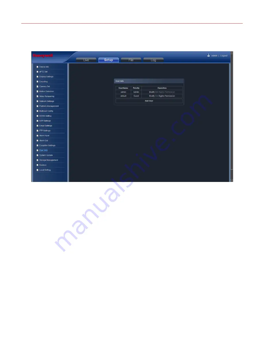
“User Info” setting interface as below, admin is the administrator (default), default 

indicates general users, booth and login with permissions authorized to default users(default). 


Figure 4-27 


  Modify:The admin user can modify the login password, the default guest user can modify the login password 

and user type. While the new added user can modify user name, login password and user type. Otherwise, 
the new added user can select None/Guest/Operator three types, and set the different permission 
assignment in the Right Permission setting


  Del: Delete the new user


  Rights Permission: permission assignment for the default guest user and new user


  Add User: Add a new user


After al

l parameters setting completed, click “Save” and the it comes into effect immediately. 

Summary of Contents for HEIPTZ-2201W-IR

Page 1: ...Document 800 21584 Rev A Honeywell HEIPTZ 2201W IR 1080p HD Network Explosion proof PTZ Camera with IR LED User Manual ...

Page 2: ...ownload and Install ActiveX 13 Login 16 Live view 17 System specification setting 20 Device Info 20 PTZ setting 21 Display settings 22 Encoding 23 Camera set 24 Motion Detection 26 Video Tampering 27 Network Settings 27 Platform Management 28 Multicase Config 29 DDNS Setting 30 NTP Settings 31 Email Settings 32 FTP Settings 33 Exception Settings 35 User Info 36 System Update 37 Storage Management ...

Page 3: ...Honeywell ii LAN 46 Internet 48 Frequently asked questions 52 ...

Page 4: ... shock caused by inappropriate installation or operational errors Safety of transportation Ensure to protect the product from hit violent vibration and liquid erosion in the process of transportation storage or installation Environment Do not install the PTZ in the environment of extreme temperature exposed to dust or with violent vibration Do not use the PTZ in the environment where the temperatu...

Page 5: ......

Page 6: ... in accordance with the instructions This user manual serves as a reference for various models The operational instructions for each model are not specified in detail in this manual If you have any problem related to a specific model please contact the relevant professionals ...

Page 7: ......

Page 8: ... atmospheres Part 0 Equipment General requirements EN 60079 1 2007 Explosive atmospheres Part 1 Equipment protection by flameproof enclosures d EN 60079 31 2009 Explosive atmospheres Part 31 Equipment dust ignition protection by enclosure t IEC 60079 0 2007 Explosive atmospheres Part 0 Equipment General requirements IEC 60079 1 2007 Explosive atmospheres Part 1 Equipment protection by flameproof e...

Page 9: ... may appear in this manual Please refer to the following table for more details Name of a click button You should be alert to the information marked with this symbol by strictly following the instructions to avoid damages to the product s hardware and software as well as their components Notes The product pictures illustrated in this manual are for reference only They may be different from the rea...

Page 10: ...Z body and to prevent explosive gas mixtures from exploding from outside the PTZ in the case of an explosion The PTZ s explosion proof capacity is realized by controlling the enclosure strength the interfacing of the components in terms of clearance and length and the maximum surface temperature of the PTZ exterior The explosion proof enclosure after fine finishing should stand up to hydrostatic p...

Page 11: ...vironment is well ventilated and devoid of violent vibration Ensure the PTZ is placed far away from any heat object when the device is in below 10 temperature suggested equipment do power cycle again Atmospheric pressure 80 to 110KPa Ambient temperature 40 to 55 Relative humidity 95 RH 25 System Requirements Ensure LAN or Internet service is available every PC is well connected to Ethernet via NIC...

Page 12: ...4 Used to fasten the sun shields on both sides Φ4 flat washer 4 Φ4 spring washer 4 M6 30 socket head cap screw 6 Used to fasten the PTZ Φ6 flat washer 6 Φ6 spring washer 6 M6 screw nut 6 Certificate 1 Sun shield 2 Network connection implement 1 Connect reticle Allen wrench 3mm 1 Used to fasten M4 8 screws Allen wrench 5mm 1 Used to fasten M6 30 screws You can remove the protective materials from t...

Page 13: ... China Co Ltd DO NOT OPEN WHEN ENERGIZED 1 Wiper 2 Left shield camera 3 Camera body 4 External entry device of the PTZ 5 Sun shield 6 Viewing window 7 Right shield illuminator 8 Nameplate 9 Label for grounding 10 Base Overall Dimension Honeywell Security China Co Ltd DO NOT OPEN WHEN ENERGIZED unit mm ...

Page 14: ...Honeywell 7 Base Dimension unit mm ...

Page 15: ...sure all the explosion proof parts are free from crack and defect which may reduce the explosion proof capacity Make sure the interior and exterior grounding is available 2 Protection of the flameproof surface Protect the flameproof surface from damages bump and scratches in the process of installation operation and maintenance 3 Grounding Make sure the interior and exterior of the PTZ is properly...

Page 16: ...e without Jamming with the composite cable coming from the camera housing 3 Match the 6 screw holes in PTZ base with the 6 screw holes in the sun shield Put the M6 30 socket head cap screws through the screw holes and fasten the screws via Φ6 spring washers Φ6 flat washers and M6 screw nuts ...

Page 17: ...on proof flexible tube and then enter the junction box for wire harness connection the overall effect is as follows PTZ EXPLOTION CAMERA SET MOUNTING BOLT NUT POLE HEWJ400 WASHING SYSTEM CEMENT BASE EXPLOTION CABLE CONDUIT EXPLOTION JUNCTION BOX EXPLOTION CABLE CONDUIT ...

Page 18: ... the holder and the explosion proof junction box must be more than 5 thread above Cable Connection If the voltage fluctuation is out of the range of 15 to 10 the camera should be provided with a voltage regulator whose nominal power should be no less than 1 5 times its service power A Surge Protective Device SPD should be applied to the aerial cable end that enters the monitoring room or the cable...

Page 19: ...e harness connection after check and confirm the guard securely installed check the wiring harness is connected correctly check the power supply and confirm the good ground confirm the live parts of terminals or more exposed no short circuit or short circuit to ground confirm the terminal connection plug connector and screw are no loose fastening ...

Page 20: ... parameters of all the dome cameras in connection with the host computer Users can modify IP addresses and other parameters by double clicking the IP addresses Before accessing the IP camera via Internet Explorer you need to configure the network settings of the host computer in the same LAN with the IP camera e g IP address 192 168 1 188 Subnet mask 255 255 255 0 Gateway 192 168 1 1 Figure 4 1 Do...

Page 21: ...When prompted Downloading Activex Control click the icon to install the Activex control as shown in the follow figure 4 2 Figure 4 2 A file download dialog will pop out click Next to installation As figure 4 3 Figure 4 3 Select the ActiveX installation and storage file the default installation and storage file is c Program Files webactivex i8 and click Next to enter next dialog As figure 4 4 ...

Page 22: ...Honeywell 15 Figure 4 4 Click Install to enter into the next dialog As figure 4 5 Figure 4 5 Click Finish to complete the ActiveX installation As figure 4 6 ...

Page 23: ...ess http 192 168 1 188 of the Network High Speed Dome to turn to login page enter username default setting is admin and password default setting is123456 click login to enter into main interface see Figure 4 7 Figure 4 7 Please refresh the page and login again if the operation process in case of power cuts ...

Page 24: ...ight wiper spray setting etc SNAP click button snap the current image and save it in JPG format automatically to the storage directory of snapped images The default path is C Program Files PREVIEW and the storage path is changeable Full Screen Live preview in full screen press keyboard ESC or double click left mouse button to exit from full screen display Record ON OFF selectable When select ON th...

Page 25: ...ise Click to call setted cruise scan Tracking path setting Select a number at the tracking drop down list click and do a serious PTZ operation then click to save and exit the tracking path setting Call tracking path Select a number at the tracking drop down list click to call tracking path Linear Select a number at the linear drop down list click to set the linear scan initial position and do a se...

Page 26: ...ter after 3 seconds PTZ will rotate to spray position preset during the time After it arrive at the preset the spray and wiper will turn on at the same time and the spray will turn off after 3 seconds while the wiper will turn off after it wiper for 3 rounds After finish all above they will get back to their positions Under the condition of the Manual spray mode user click Manual button the spray ...

Page 27: ...Operation 20 Figure 4 11 System specification setting Device Info Network High Speed Dome Device Info interface as figure 4 12 ...

Page 28: ...r Version Display the software version date Hardware Version Display the hardware version number Format Switch to select the PAL and NTSC image scanning system Device Time Set and display the device current time After all parameters setting completed click Save and then it comes into effect immediately PTZ setting Network High Speed Dome ePTZ Set interface as figure 4 13 ...

Page 29: ...n method Connect analog high speed dome at the Network High Speed Dome AB port set the protocol and baud rate and control the high speed dome through IPC preview interface After all parameters setting completed click Save and the it comes into effect immediately Display settings Network High Speed Dome Display settings interface as figure 4 14 ...

Page 30: ...e appointed channel Contrast Adjust the contrast for the appointed channel Saturation Adjust the saturation for the appointed channel Hue Adjust the hue for the appointed channel Cyclotron arrow Restore the default parameters Title Location Set the channel title location for the appointed channel Date Adjustment Set the channel date location for the appointed channel After all parameters setting c...

Page 31: ... rate in the drop down list Video Encode H 264 MJPEG two kinds of video encode format H264 Profile Mainprofile Baseline Highprofile I frame Interval Set the I frame internal time Bitrate Type Constant Variable selectable Bitrate Set different bitrate for different channels After all parameters setting completed click Save and the it comes into effect immediately Setup setting will change the front...

Page 32: ...al Mirror Vertical Mirror 180 rotation selectable default is Normal Backlight mode Close WDR Backlight correction selectable default is Close Intensity Low Mid High selectable It is invalid when Backlight mode set close Dark compensation Close Low Mid High selectable default is Mid DNR mode Close Low Mid High selectable default is Mid Zoom rate Show Hide selectable set the zoom rate and view the c...

Page 33: ...g Click Drawing then set the detective area Clear Click Clear to clear the current detective areas Sensitivity The higher of the sensitivity the obvious of the motion detective Email Send Email to appointed mailbox when alarm triggered Snap Snapshot and install the picture in the HDD when alarm triggered Alarm Output There is a warner connect the alarm output port alarm triggered the embedded rela...

Page 34: ... when alarm triggered Snap Snapshot and install the picture in the HDD when alarm triggered Record Video record and installed in the HDD or send as FTP to keep when alarm triggered Alarm Output There is a warner connect the alarm output port alarm triggered the embedded relay switch to make alarm output Enable PTZ Alarm input to link the PTZ motion Preset Alarm input to link the preset Snap Interv...

Page 35: ...s device connected on the network SNMP Manager IP Input the corresponding SNMP manager IP address HTTP Port Input the corresponding port Default is 80 HTTPS Port Input the corresponding port Default is 4433 Enable UPnp When click Enable UPnp the device and HTTP port will mapping to the router automatically Device Port Input the corresponding device port Default is 5050 Enable PPPOE Click to enable...

Page 36: ...Honeywell 29 Figure 4 20 User can open close edit delete the protocol Multicase Config Network High Speed Dome Multicast Config interface as figure 4 21 ...

Page 37: ... address port TTL of primary stream video audio and sub stream video audio DDNS Setting DDNS is implemented through a dynamic domain resolution server It requires a PC with fixed IP address on the Internet on which the dynamic domain resolution server runs Network High Speed Dome network setting interface as below ...

Page 38: ...types selectable Server Name Input server name for example member 3322 org Port Input port No Username Input user name Password Input password Confirm pwd Input the password again to confirm it Domain Input the standby domain After all parameters setting completed click Save and the it comes into effect immediately NTP Settings Network High Speed Dome NTP Settings interface as figure 4 23 ...

Page 39: ... Port default is 123 Adjust time interval Input the interval time Select Time Zone Different area time format selectable GMT Adjust the time more exact After all parameters setting completed click Save and the it comes into effect immediately Email Settings Network High Speed Dome Email Settings interface as figure 4 24 ...

Page 40: ... Input the smtp server address of the outbox SMTP Port Input the smtp server port of the outbox Sending interval Input the sending interval time Receiver Input the mail receiver name Email Addr Input the address of the inbox After all parameters setting completed click Save and the it comes into effect immediately FTP Settings Network High Speed Dome FTP Settings interface as figure 4 25 ...

Page 41: ...er Address Input the upload server address Port Input the server port default is 21 Username Input the upload username Password Input the upload password Path Input the upload file path After all parameters setting completed click Save and the it comes into effect immediately ...

Page 42: ...broken IP address conflict Illegal access video signal exception types selectable Record Click Record it will do video record as any exception type triggered the alarm output Alarm Click Alarm Output it will Linkage other alarm devices as any exception type triggered After all parameters setting completed click Save and the it comes into effect immediately ...

Page 43: ... guest user can modify the login password and user type While the new added user can modify user name login password and user type Otherwise the new added user can select None Guest Operator three types and set the different permission assignment in the Right Permission setting Del Delete the new user Rights Permission permission assignment for the default guest user and new user Add User Add a ne...

Page 44: ...eed Dome System Update setting interface as figure 4 28 Figure 4 28 File Click Browse to find and select the upgrade kit then click Update Non technician should not try to operate system upgrade do not turn off the power during upgrade process ...

Page 45: ...nt Network High Speed Dome Storage Management setting interface as below you can check current HDD capacity spare capacity status and do HDD formatting Note Turn off the power supply when insert or take out the TF card Figure 4 29 ...

Page 46: ...Honeywell 39 Restore Network High Speed Dome Restore setting interface as figure 4 30 Figure 4 30 Restore Restore to factory setting Reboot Reboot the devices ...

Page 47: ...pture Select the preview capture file storage path File Download Select the download file storage path Rec Capture Select the preview video record file storage path Record File Type AVI format selectable Color Realtime Smooth way two types selectable and the value is settable After all parameters setting completed click Save and the it comes into effect immediately ...

Page 48: ... to play the backup video image file Stop Click button to stop the the play Slow Click button to slow play the backup video image file Fast Click button to fast play the backup video image file Frame Click button to play the backup video image file by frame Capture Click button to snap the backup video image during display Download Click button to download the backup video image file Voice Click b...

Page 49: ...ce as figure 4 33 Figure 4 33 Main Type There are All Alarm Exception Settings Operation Additional Information four types selectable Start Time Set the start time End Time Set the end time Page Num Set the log numbers on each page Search Search the corresponding logs ...

Page 50: ...c Range ON OFF OSD Overlay Name date time Position adjustable IP Specification Video Compression H 264 Main Profile Motion JPEG simultaneously Image Resolution Main stream HD1080P 1920x1080 HD720P 1280x720 Q1080P 960x540 Sub stream HD720P 1280x720 VGA 640x480 Q1080P 960x540 QVGA 320x240 Q720P 640 360 D1 QICF ICF Bit Rate CBR VBR Audio Compression G 711 64Kbps Supported Protocol IPv4 IPv6 TCP UDP H...

Page 51: ... Alarm input Motion detection Video tampering Electrical Power Supply AC24V Power Consumption 100W Mechanical Dimensions 498mm L 310mm W 377 5mm H Weight Approx 33 Kg Local Storage disable Connector RJ 45 10BaseT 100BaseTX AC24V jack reset switch Environmental Protection Class IP68 2m 1h Operating Temperature 40 C 55 C Operating Humidity 95 RH 25 Viewing System Browser IE 8 0 or above Video Player...

Page 52: ...erver runs All internet users can view the Network High Speed Dome via a fixed IP address TCP 80 Web port 5050 Communication port audio video data transmission port talkback data transmission port UDP 5050 Audio video data transmission port Multi cast port 28080 Main stream 28081 Sub stream Onvif port 80 Rtsp port 554 RTSP port 8002 Search port 10000 Telnet port 23 Onvif search port 3702 Video str...

Page 53: ...ections will tell you how to operate the Network High Speed Dome through LAN WAN LAN There two ways to connect Network High Speed Dome Static IP Dynamic IP Static IP Static IP means the webmaster distribute a LAN inner IP address to the Network High Speed Dome Keep your PC IP address same as the camera IP address and to implement access Network topological graph as follows Network setting referenc...

Page 54: ...in subnet mask the default is 255 255 255 0 4 Fill in gateway address the default is 192 168 1 1 After input all parameters click Save then the device restart Input the device IP address at the IE browser to visit the camera Dynamic IP Dynamic IP means that Network High Speed Dome obtains IP address from DHCP server See below picture for the network topology Please refer to below picture for the n...

Page 55: ...ee ways to connect Network High Speed Dome to the Internet 1 Fixed IP mode 2 ADSL broadband and router share online mode Dynamic get the IP address mode 3 PPPOE dial up access After Network High Speed Dome is connected to Internet remote Internet users can visit it directly via domain name or IP address Fixed IP mode See below picture for the network topology Please refer to below picture for the ...

Page 56: ...h Speed Dome remotely via entering http 218 84 31 168 to IE browser Broadband and router sharing Internet access mode dynamic obtainment of extranet IP address mode like ADSL and so on If you select router dial up to connect internet see below picture for the network topology Users can set up DDNS domain name service at the same time Fill the username and password which were applied in the DDNS se...

Page 57: ...ut the domain name applied on the DDNS server such as video no ip net 7 Input the DDNS address such as dynupdate no ip com 8 Input the DDNS port default is 80 Suggested users keep it After all parameters setting completed click Save and devices comes into effect Port mapping setting procedure TP LINK TL WR340G illustration 1 Ask network administrator for the IP address of the router i e LAN gatewa...

Page 58: ... Servers as below picture shows 3 Select Add New Items enter the IP address of the Network High Speed Dome e g 192 168 1 100 port e g 85 status valid and other information click save see below picture 4 After save successfully below screen appears ...

Page 59: ...to IE browser Frequently asked questions 1 No video image displayed in IE browser Possible reason ActiveX not installed Solution ActiveX must be installed when visiting Network High Speed Dome for the first time via Internet Explore How to install Visit Network High Speed Dome click Download Address file download dialog will pop up select Run or Save to download After download finishes installatio...

Page 60: ...settings of Gateway Possible reason 4 Physical address of network conflict with Network High Speed Dome Solution Modify the physical address of Network High Speed Dome Possible Reason 5 Web port has been modified Solution Contact Network Administrator to obtain related information 5 The color of images is abnormal green or other colors Sometimes Network High Speed Dome images cannot display proper...

Page 61: ...dup AGP veins speedup in DirectX function If they cannot be enabled that means DirectX installation fails or hardware not supportive Table composite cables NUMBER DESCRIPTION COATING MATERIAL LINE OF CORE WIRE SIZE WIRE LENGTH NOTE Composite Cable PU 1 Ethernet Cable PVC 4 groups of shielded twisted pair cable 26AWG Fixed length 1150mm 2 Reset Cable PVC 1 groups of shielded twisted pair cable 26AW...

Page 62: ...06012 13 Email security ea honeywell com https www asia security honeywell com Thailand office 252 121 25th Floor Muang Thai Phatra Office Tower II Ratchadapisek Road Huay Khwang Bangkok Thailand 10320 Tel 66 2 693 3099 Email security ea honeywell com https www asia security honeywell com Indonesia Office Sastra Graha 5th Floor Suite 509 Jalan Raya Pejuangan No 21 Jakarta Indonesia 11530 Tel 62 21...

Reviews: