background image


EXCEL 100C INSTALLATION INSTRUCTIONS


EN1R-0144GE51 R1007 


Trademark Information


Echelon, LON, L

ON

M

ARK

, L

ON

W

ORKS

, LonBuilder, NodeBuilder, LonManager, 

LonTalk, LonUsers, LonPoint, Neuron, 3120, 3150, the Echelon logo, the L

ON

M

ARK


logo, and the LonUsers logo are trademarks of Echelon Corporation registered in 
the United States and other countries. LonLink, LonResponse, LonSupport, and 
LonMaker are trademarks of Echelon Corporation. 


Summary of Contents for Excel 100C

Page 1: ...Copyright 2007 Honeywell Inc All Rights Reserved EN1R 0144GE51 R1007 Excel 100C CONTROLLERS HONEYWELL EXCEL 5000 OPEN SYSTEM INSTALLATION INSTRUCTIONS ...

Page 2: ...RKS LonBuilder NodeBuilder LonManager LonTalk LonUsers LonPoint Neuron 3120 3150 the Echelon logo the LONMARK logo and the LonUsers logo are trademarks of Echelon Corporation registered in the United States and other countries LonLink LonResponse LonSupport and LonMaker are trademarks of Echelon Corporation ...

Page 3: ...and Cross Sectional Areas 13 Line Power Supply 14 Communication 14 ELECTRICAL CONNECTION 16 Terminal Assignment for Digital Inputs 18 Terminal Assignment for Relay Modules 19 Terminal Assignment for Relays and Actuators 21 Connection of Alarm Relays 22 Normally Open Normally Closed Attribute 22 System Bus C Bus 23 Connections to Operating Device 24 REMOTE COMMUNICATIONS 30 Modem or ISDN Terminal A...

Page 4: ...Equipment 35 GSM Antenna Installation 37 M20 Terminal Set Up 37 BACKLIGHT 39 DIMENSIONS 40 U S SPECIFICATIONS 42 Electrical Connection of Sensors 42 Transformers 44 Cables 44 Relays 45 Repeaters 45 EUROPEAN SPECIFICATIONS 46 Electrical Connection of Sensors 46 Transformers 49 Relays 49 Cables 49 Repeaters 50 ...

Page 5: ...n amended to encompass all XI581 582 models and all references to XI584 have been changed to XL Online 28 In section Operator s Unit XI582 figures have been modified to reflect hardware changes NOTE The Excel 100 has been developed to meet control requirements worldwide Some referenced applications accessories have been developed to meet specific regional requirements and may not be available or a...

Page 6: ...p by step Follow instructions in accordance with the progress of the assembly step by step Skip sections only when requested to do so in the text Technical Requirements All devices ready Assembly can start only if all system components have been installed and are ready to be operated and the control and measuring sensor cables have been connected to the control cabinet All cables laid All cables m...

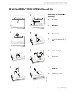
Page 7: ...1 R1007 DEVICE ASSEMBLY AND SYSTEM INSTALLATION Assembly of Controller Housing 1 Open cover 2 Remove tool 3 Remove screw 4 Loosen housing cover from base 5 Loosen front right 6 Loosen rear 7 Loosen left 8 Lift housing off base 3 2 1 4 5 6 7 8 CB 0700 Mb ...

Page 8: ...ce optional Electrical connection see pages 10 19 to 21 5 Set the bus termination switch on the back of the housing according to the system configuration see page 14 for details 6 Fit housing Make sure it is straight 7 Connect operating device see pages 24 and up IMPORTANT Set the port selector switch left to the sub D port according to whether the front port or the rear terminals should be active...

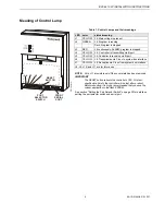
Page 9: ...ia C bus to system bus interface L7 YELLOW Lit Reception via C bus from system bus interface L8 L9 L10 and L11 are for future use NOTE L4 to L11 are visible only if the cover plate has been removed IMPORTANT The RESET button reboots the controller s CPU All plant specific data held in the controller will be lost after a reboot Before rebooting it is highly recommended that you save the current app...

Page 10: ... short circuiting After short circuiting it takes time approx 60 sec for voltage to recover reserved common GND DTR DCD C C 5 V Xi582 RTS modem analog input analog input digital input digital input AO 1 xx0401 AO 2 xx0402 AO 3 xx0403 AO 4 xx0404 AO 5 xx0405 AO 6 xx0406 AO 7 xx0407 AO 8 xx0408 AO 9 xx0501 AO 10 xx0502 AO 11 xx0503 AO 12 xx0504 DI 7 xx0307 DI 8 xx0308 DI 9 xx0309 DI 10 xx0310 DI 11 ...

Page 11: ...this period of time all RAM data and time information are lost Cable Routing Minimum distance to mains cables 10 mm 0 4 in All signal and output cables low voltage should be regarded as communication circuits in accordance with VDE 0100 VDE 0800 and NEC it should therefore be routed separately from line voltage Minimum distance 10 cm 4 in for unshielded cable Minimum distance 10 mm 0 4 in for shie...

Page 12: ...e cables are available XW565 XW582 XW583 with the shield already connected to the computer module plug end For detailed information on cable types to be used in accordance with regional requirements please refer to the U S and European Specifications chapters System Ground WARNING High voltage Risk of electrical shock or equipment damage The controller s system ground must have no connection with ...

Page 13: ...und For detailed information on cable types to be used in accordance to regional requirements please refer to the U S and European Specifications chapters Cabling of Actuator with 24 Vac Supply and max 550 ft 170 m TRANSFORMER MAX 550ft 170m MIN 14AWG 2 5mm 2 PRIMARY VOLTAGE Y GND 24 Vac 24 V 0000056c Cabling of Actuator with 24 Vac Supply from External Transformer and max 1 300 ft 400 m If the di...

Page 14: ...detailed information on transformers to be used in accordance to regional requirements please refer to the U S and European Specifications chapters Standard Transformers Requirements for standard transformers Table 3 Requirements for standard transformers output voltage impedance AC current 24 5 Vac to 25 5 Vac 1 15 Ω max 2 A 24 5 Vac to 25 5 Vac 0 40 Ω max 6 A 24 5 Vac to 25 5 Vac 0 17 Ω max 12 A...

Page 15: ... middle max 76 8 Kbaud middle of C Bus XD508 XL20XD508 down max 76 8 Kbaud beginning or end of C Bus XD508 XL20XD508 NOTE Modules listed in the Compatibility column are used in Excel 20 100B 500 600 Controllers Connection to modem This figure shows the connection between Excel 100C and modem via cable XW571 see page 31 for details Lightning Protection Please check with your local Honeywell represe...

Page 16: ...0 Vdc 24 Vac 12 bit resolution 75 mV accuracy 0 to 10 V Accuracy of Analog Input Sensors Table 5 Accuracy of analog input sensors in relation to temperature measurement error Kelvin without sensor tolerance range Pt1000 NTC 20k ohms 58 to 4 F 50 to 20 C 1 2 K 5 0 K 4 to 32 F 20 to 0 C 0 7 K 1 0 K 32 to 86 F 0 to 30 C 0 5 K 0 3 K 86 to 158 F 30 to 70 C 0 7 K 0 5 K 158 to 212 F 70 to 100 C 1 2 K 1 0...

Page 17: ... YES case 2 8 89 V XF526 fixed NO NO YES case 2 8 89 V XFL521 XFL521A B 10 V YES 3 config 6 case 1 8 89 V Smart I O XFC 5 V optional switch off YES 4 YES YES 7 case 3 5 V 0 V XL20 fixed NO YES case 2 8 89 V XL50 optional switch off YES 2 YES 5 case 1 0 V XL100 XL100A fixed NO YES case 2 8 89 V XL100B NO YES configurable XL100C 10 V optional switch off YES 1 NO NO YES 5 case 1 8 89 V 0 V 1 controll...

Page 18: ...all below 2 5 V so that the digital status 0 is transmitted Ri 15 kΩ IMPORTANT Line voltage must not be present at any of the terminals under any circumstances Devices with 110 V 230 Vac must be isolated by a transformer Six additional digital inputs are available at the terminals 49 to 54 for switching to I J or K Table 7 Use of input terminals as counter inputs input terminals frequency pulse du...

Page 19: ...see above 0 1 mA max sink output current Protected inputs up to 24 Vac 8 bit resolution 100 mV 1 LSB accuracy 1 LSB 43 mV 100 mV 1 LSB zero point 1 LSB 43 mV The relay modules are supplied via the special relay connection of the controller terminals 65 66 IMPORTANT Important during connection 1 Correct polarity 2 Under no circumstances may a relay module be connected to the reference voltage Sever...

Page 20: ... 17 controls the changeover con tact K2 Terminal 18 controls the change over contact K1 IMPORTANT It is not allowed to draw more than 300 mA out of terminal 65 66 The number of MCE and MCD modules that can be used depends only on the available AOs This means 5 MCE 15 relays incl watchdog alarm terminal 69 or 6 MCD 12 relays ...

Page 21: ...dance of the relay must be a min of 500 Ω for an output voltage of 11 V an impedance of less than 500 Ω can cause erroneous output voltage The output current is limited up to max 20 mA O Type of connector for actuators with standard input signal 0 to 20 mA but the sensor input impedance must be 500 Ω Each channel can be used as an analog output 0 to 10 V or respectively as current output 0 to 20 m...

Page 22: ...ines the relation between the physical states contact position and relay ON OFF respectively at the digital inputs and outputs and their logical status see also Table 8 and Table 9 Table 8 Digital input parameters contact position NO NC attribute logical status input voltage open NO 0 2 5 V closed NO 1 5 V open NC 1 2 5 V closed NC 0 5 V Table 9 Digital output parameters relay ON OFF NO NC attribu...

Page 23: ... rate again NOTE When adding or removing a controller to from the C Bus it may take up to two minutes to re initialize the bus During this time communication on the C bus is lost See page 14 for details on setting the C Bus termination on the Excel 100C IMPORTANT For communication with more than 9600 baud it is required to enable the termination of the first and the last device on the C bus see pa...

Page 24: ... to XL100C rear to XI582 XW583 SHIELD RxD GND 5VE TxD YELLOW GRAY not used BROWN GREEN WHITE 1 4 3 2 19 20 21 22 25 EXCEL 100C XW582 XW583 XI582 XI582 The XI582 operator s unit can be connected to either the front connector using the XW582 cable or the rear terminals using the XW583 cable of the Excel 100C XW582 cable length 15 ft 5 m XW583 cable length 15 ft 5 m NOTE The controller will warm star...

Page 25: ...uter 1 5 4 3 2 9 8 7 6 to XL100C to XL Online 1 5 4 3 2 9 8 7 6 XW585 SHIELD RxD GND TxD EXCEL 100C XW585 PC with XL Online A tailor made cable for the Excel 100C controller is available with plugs on both ends XW585 XW585 cable length 16 ft 5 m NOTE You can also use a standard Null modem cable ...

Page 26: ...CEL 100C INSTALLATION INSTRUCTIONS EN1R 0144GE51 R1007 26 Adapter Cable XI582 and XL Online to Excel 100B and C EXCEL 100C EXCEL 100C EXCEL 100B EXCEL 100B XW585 XW585 XW585 XW585 PC with XL Online XI582 ...

Page 27: ... is a mix of Excel 100C and Excel 100B controllers Always use the new cables XW582 and XW585 with the Excel 100C and the additional adapter cable XW584 for connecting to the Excel 100B 1 2 3 4 5 9 6 7 8 shield shield shield TxD 5VE RxD GND green brown yellow white TxD yellow 5VE brown RxD green GND white XW 584 1 3 2 4 5 6 7 8 9 10 not connected 4x 9 Code Pin ...

Page 28: ...nserting tip of an awl or a similar narrow pointed object into the small hole on one side of the operator terminal When the latch releases insert the awl into the small hole on the other side of operator terminal and pry off the cover A B A B 2 Route cable from the Excel 100C TxD CPU BROWN GREEN WHITE YELLOW VE RxD CPU GND A B ...

Page 29: ...ALLATION INSTRUCTIONS 29 EN1R 0144GE51 R1007 3 If mounting on a wall remove feet 4 Attach the housing to the wall 5 Make electrical connections black gray wire not used TxD CPU BROWN GREEN WHITE YELLOW VE RxD CPU GND ...

Page 30: ...rear terminals If the switch is set to front port the rear terminals are deactivated and vice versa Front port Rear terminals active active REMOTE COMMUNICATIONS For remote communications with up to three XBS Building Centrals a modem or ISDN terminal adapter can be connected directly to the front serial port or the rear terminals on the base of the Excel 100C see graphics below NOTES Remote commu...

Page 31: ...em Requirements Modem must support Hayes compatible command set not V150 or V151 Microsoft command set Modem must support alpha numeric return codes Modem must follow serial baud rate of the controller Modem must support auto bauding baud rate fall back When carrier detect connect is reported the carrier must be on simultaneously at both modems on controller side and on XBS side use same modem Aft...

Page 32: ...SET MODEM command in the Start Up sequence on the MMI This will allow a quick and easy modem reset without having to run the modem set up software or the Windows terminal program The RESET MODEM command causes the following commands to be sent to the modem 1 ATZ executes hardware reset on modem 2 AT FX3 W resets modem to factory configuration settings configures the modem to not wait for the publi...

Page 33: ...ting In case of any problems the handbook of the modem or ISDN terminal adapter must be consulted A Frequently Asked Questions and Troubleshooting document is available via the Honeywell Technical Assistance Center TAC or for Honeywell employees on the HIVE under Technical Assistance Center Controllers Excel 80 and 100 and 500 and 600 technical literature modemfaq doc or on the Docu Server under h...

Page 34: ...al can endanger navigation it interferes with the cellular network and it is illegal Failure to comply with this prohibition may lead to temporary suspension or permanent cancellation of Cellular Engine services for the person who disregards this prohibition and or to legal action against said person CAUTION Users are advised to NOT use the M20T in automotive service stations Users are reminded of...

Page 35: ... HOLES TOP BOTTOM HANDSET INTERFACE Mechanical characteristics Weight 145 g Dimensions max LxWxH 107 0 x 63 5 x 31 3 mm Temperature range 20 C to 55 C Protection class IP40 Mechanical vibrations Amplitude 7 5 mm at 5 to 200 Hz sine Max pulse acceleration 30 g pulse with 18 ms duration Air humidity 5 98 Electrical characteristics Operating voltage range 8 to 28 8 Vdc 5 ripple Undervoltage overvolta...

Page 36: ...X max 1 9 1 installed Gain 1 5 dB referenced to λ 2 dipole 3dB width of cone vertical 80 horizontal 360 Maximum power 1 W cw 2 W peak at ambient temperature of 55 C Depending on the application and the RF field at the local site the GSM antenna may be mounted directly or via cable The maximum antenna cable length is 8 0 m including 20 cm M20 Terminal cable NOTE The maximum number of push pull cycl...

Page 37: ... antenna signal Ideally within a range of approximately 3 meters there should not be any vertical barriers that would block the antenna signal such as doors PCs cupboards etc Select the most suitable antenna Location and mounting limitations may require that special antennas be used such as antennas with higher amplification or directional antennas Avoid loose contacts All connections from the M20...

Page 38: ...T dials out on the telephone number for data communi cation otherwise its call will not be recognized by the XBS The M20T can be forced to do so by adding the letter i to the telephone number e g ATDi1234567891234 NOTE As soon as the PIN is entered into the Excel controller the following mechanisms will take place automatically Cyclical check once per minute for existence of the PIN number in the ...

Page 39: ...CTIONS 39 EN1R 0144GE51 R1007 BACKLIGHT Pressing any of the eight operating keys activates the backlight If no entries are made for approximately two minutes the backlight turns itself off automatically until a key is pressed again ...

Page 40: ...144GE51 R1007 40 DIMENSIONS 192mm 7 56in 192mm 7 56in 235 mm 9 25 in 142 mm 5 59 in 72 mm 2 83 in Excel 100C MCD 3 MCE 3 XI582AH 95 mm 3 74 in 42 mm 1 65 in MCE 3 MDE 3 48 mm 1 89 in 93mm 3 66in 40 mm 1 57 in 170mm 6 69in 80 mm 3 15 in CB 0285b ...

Page 41: ...IN EN 50 022 35x15 for wall mounting use screw holes located in the top center and bottom corners Basdim_1 Base XI582AH wall mounting 40 mm 1 57 in 124 mm 4 88 in 216 mm 8 5 in 36 mm 1 42 in 96mm 3 78in Cable hole 190mm 7 48in 96mm 3 78in 95mm 3 74in 95mm 3 74in 24 mm 0 94 in 141 mm 5 55 in 12 mm 0 47 in 105 mm 4 13 in 166mm 6 54in 12mm 0 47in 12mm 0 47in ...

Page 42: ...rs 20 kΩ Example Room temperature sensors T7589 T7770A Discharge Hot or Chilled Water sensors C7031B C D Outside Air temperature sensor C7031F B Type of connection for active sensors with standard output signal 0 to 10 V Example Humidity sensor C7600B C Type of connection for active sensors with standard output signal 0 4 to 20 mA to be clamped down with a connector resistor R1 499 Ω 0 25 Example ...

Page 43: ...ver contact of an additional relay Unconnected analog inputs have a default voltage of 8 5 V This is interpreted by the controller as a logical status of 1 This means that in general no external relay is needed for normally closed contacts NOTE The relay contact must be suitable for switching low voltage For long cable distances the analog input signal may be sensitive to interference In this case...

Page 44: ...nds mainly on the baud rate There are regional differences as to whether shielded or unshielded cable must can be used The table below summarizes cable types and gives selection guidance Note that baud rate and maximum bus length are related to each other NOTE In the U S shielded or unshielded cable may be used Table 12 Cable specifications max baudrate max bus length cable type description recomm...

Page 45: ...of the single bus length The table below summarizes the number of repeaters allowed Note that the maximum length depends on the cable specification as described under the cables chapter Table 13 Max baud rate in relation to cable length and no of repeaters max baud rate max no of repeaters resulting max bus length depends upon cable specifications 76 8 Kbaud 5 7 200 m 24 000 ft The repeater is ava...

Page 46: ... Example Room temperature sensor RF 20 Inlet temperature sensor VF 20 A External temperature sensor AF20 B Type of connection for active sensors with standard output signal 0 to 10 V Example Humidity sensor HKT 1 HRT 1 C Type of connection for active sensors with standard output signal 0 4 to 20 mA to be clamped down with a connector resistor R1 499 Ω 0 25 Example Immersion temperature sensor VF 1...

Page 47: ...Sun sensor SAF25 D To measure the wind effect wind sensor WS21 should be used E To measure the solar effect the SAF 25 sun sensor should be used In order to operate the SAF 25 the reference voltage from terminal 67 of the controller device must be connected to terminal 2 SAF 25 ...

Page 48: ... analog inputs have a default voltage of 8 5 V This is interpreted by the controller as a logical status of 1 This means that in general no external relay is needed for normally closed contacts NOTE The relay contact must be suitable for switching low voltage For long cable distances the analog input signal may be sensitive to interference In this case an external relay may also be used for normal...

Page 49: ...cification depends mainly on the baud rate The table below summarizes cable types and gives selection guidance Note that baud rate and maximum bus length are related to each other Table 16 Cable specifications max baudrate max bus length cable type description recommended for J Y ST Y Europe 76 800 1200 m 2 x 2 x 0 8 shielded twisted pair Inside cabinet only A Y ST Y Europe 76 800 1200 m 2 x 2 x 0...

Page 50: ...nnected to terminal 15 and 18 or 33 and 36 per following figure CB 0492 X1 15 16 17 18 15 16 17 18 15 16 17 18 33 34 35 36 XC5010C XC6010 XC5010C XC6010 XC5010C XC6010 Excel 100 Repeaters Each repeater extends the bus length by the amount of the single bus length The table below summarizes the number of repeaters allowed Note that the maximum length depends on the cable specification as described ...

Reviews: