


EAGLEHAWK NX CONTROLLER – INSTALLATION & COMMISSIONING INSTRUCTIONS
EN1Z-1039GE51 R1218
44
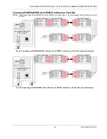
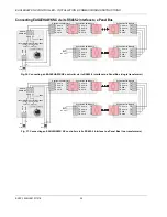
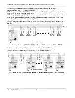
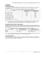
Connecting EAGLEHAWK NX via its RS485-1 Interface to a Modbus
With regards to Fig. 49, please note the following:
NOTE:
Always power each EAGLEHAWK NX controller and the connected Modbus slaves via separate transformers.
NOTE:
For "L," see section "RS485 Standard" on pg. 10.
NOTE:
If any of the devices are electrically isolated, it is recommended that those devices be connected to signal ground. See
section "RS485 Standard" on pg. 10.
Example: EAGLEHAWK NX Modbus Master Controller and Connected Modbus Slaves (with inserted
termination resistor)
1 2
24
V
~
24
~0
242526
F1
230 V
24 V
L
GND-1
GND-1
+5V
ISO
RS485-1 (+) RS485-1 (-)
550 OHM
150 OHM
550 OHM
END
END
BI
A
S
MI
D
Modbus
Module #1
Modbus
Module #2
RS
485
+
RS
485
-
GN
D
Modbus
Module #3
Modbus
Module #4
Modbus
Module #N-1
Modbus
Module #N
RS
485
+
RS
485
+
RS
485
+
RS
485
-
RS
485
-
GN
D
GN
D
GN
D
R
T
RS
485
-
RS
485
+
RS
485
-
GN
D
*CONNECT GND, IF AVAILABLE.
120 OHM
EAGLE-
HAWK NX
Fig. 49. Connection of an EAGLEHAWK NX Modbus master controller via its RS485-1 interface to a Modbus with slaves
The termination resistor must be inserted directly into the terminals of the last Modbus slave.
NOTE:
In this example, any or all of the Modbus RTU slaves depicted here can be EAGLEHAWK NX Modbus RTU slaves. In
such cases, an EAGLEHAWK NX Modbus RTU slave positioned at the end of the Modbus (as "Modbus Module #N")
must have its 3-position slide switches set to "End" (see Fig. 16) (the insertion of the aforementioned termination
resistor is then unnecessary) and any EAGLEHAWK NX Modbus RTU slaves positioned elsewhere on the Modbus
must have their 3-position slide switch set to "Mid" (see Fig. 14).