


EAGLEHAWK NX CONTROLLER – INSTALLATION & COMMISSIONING INSTRUCTIONS
EN1Z-1039GE51 R1218
32
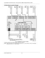
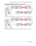
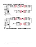
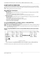
PANEL BUS CONNECTION
The EAGLEHAWK NX controller features two RS485 interfaces to which Panel Bus modules can be connected: RS485-1
(consisting of push-in terminals 24 [GND-1], 25, and 26) and/or RS485-2 (consisting of push-in terminals 29, 30, and 31 [GND-
2]).
NOTE:
GND-2 is internally connected with 24V-0 (terminal 1)
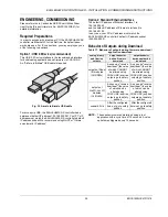
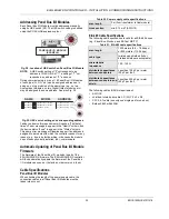
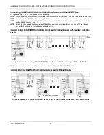
Overview of Panel Bus I/O Modules
XS821-22
XSU821-22
XS823
XSU823
XS824-25
XSU824-25
EAGLEHAWK NX
PANEL BUS
PANEL BUS
PANEL BUS
PANEL BUS
PANEL BUS I/O
ELECTRONIC
MODULES
pluggable
ANALOG OUTPUT
pluggable
ANALOG INPUT
pluggable
BINARY INPUT
pluggable
FLOATING
OUTPUT
CLIOP821A
CLIOPR822A
CLIOP822A
CLIOP823A
pluggable
RELAY OUTPUT
CLIOPR824A
CLIOPR825A
CLIOP824A
MIXED I/Os
(with integrated electronic module)
1 2 3 4 5 6 7 8 9 10 11 12
B1
B2
B3
B4
B5
B6
B12
12
6
B11
11
5
B10
10
4
B9
9
3
B8
8
2
B7
7
1
DI
Binary Inputs
G1
G2
41
42
GND Analog Outputs
AI2 AI3
AI4
14
15
16
AI1
17
18
19
20
13
Analog Inputs
AO5
AO1
AO6
AO2
AO7
AO3
AO8
AO4
21
25
26
27
28
22
23
24
DO
24V Relays
NO1 NO2 NO3 NO4 NO5 NO6
CO1 CO2 CO3 CO4 CO5 CO6
35
29
30
31
32
33
34
36
37
38
39
40
1 2 3 4 5 6
Install. Instr.
MU1B-0473GE51
!
AI5
AI6 AI7
AI8
Honeywell
CLIOP830A
CLIOP830A
CLIOP831A
CLIOP831A
Fig. 33. Overview of Panel Bus I/O Modules
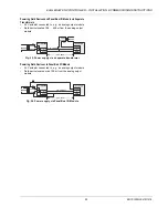
Panel Bus Considerations
RS485-1 (isolated)
-
Max. Panel Bus length:
o
40 meters. Any type of cabling and topology (including star and loop topology) possible. No additional end
termination permitted.
o
1200 meters (9.6 – 78.8 kbps) or 800 meters (115.2 kbps) (see also section "RS485 Standard" on pg. 10).
Mandatory twisted-pair or telephone cable and daisy chain topology. The EAGLEHAWK NX must be positioned at
one end of the Panel Bus, and an end termination (120 Ω) at the other end. Further, the three-position slide switch
(see Fig. 13 on pg. 9) must be set to "END."
RS485-2 (non-isolated)
-
Max. Panel Bus length:
o
40 meters. Any type of cabling and topology (including star and loop topology) possible. No additional end
termination permitted.
o
1200 meters (9.6 – 78.8 kbps) or 800 meters (115.2 kbps) (see also section "RS485 Standard" on pg. 10).
Mandatory twisted-pair or telephone cable and daisy chain topology. The EAGLEHAWK NX controller must be
positioned at one end of the Panel Bus, and an end termination (120 Ω) at the other end.
-
Must not extend beyond a single building or building floor
Max. no. of Panel Bus I/O modules per RS485 interface
-
Max. no. of Panel Bus I/O modules of a given model: 16
-
Total max. no. of Panel Bus I/O modules: 64
Max. no. of Panel Bus I/O modules per EAGLEHAWK
NX
-
Max. no. of Panel Bus I/O modules of a given model: 32
-
Total max. no. of Panel Bus I/O modules: 128
Max. no. of hardware I/O points per EAGLEHAWK
NX: 1000
(given a polling rate of 2 seconds; see also section
"Controller Performance" on pg. 48)
Refer to CentraLine I/O Modules - Installation & Commissioning Instructions (EN1Z-0973GE51) for more information about
connection, current requirements, power supply, overvoltage protection, cable specifications, fusing, effects of manual overrides,
etc. of Panel Bus I/O modules and field devices connected to them.