


EAGLEHAWK NX CONTROLLER – INSTALLATION & COMMISSIONING INSTRUCTIONS
EN1Z-1039GE51 R1218
38
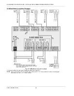
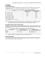
Field Devices
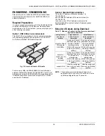
Depending on the distance from the controller, field devices
can be supplied with power by the same transformer used for
the Panel Bus I/O Modules, or by a separate transformer,
using cables as specified in Table 22.
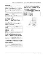
Table 22. Power / communication cable specifications
type of signal
cross-sectional area
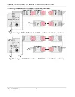
100 m (Fig. 26)
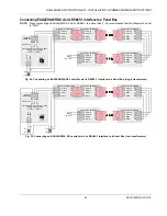
single transformer
400 m (Fig. 25)
sep. transformers
24 VAC power
1.5 mm
2
(16 AWG)
not allowed for
> 100 m (300 ft)
0…10 V signals
0.081 – 2.08 mm
2
(28 – 14 AWG)
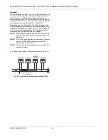
For wiring field devices, see section "Powering Panel Bus I/O
Modules and Field Devices" on page 22.
Routing Cables to Field Devices
Route low-voltage signal and output cables to field devices
separately from mains cables.
Table 23. Minimum distances to power mains cables
cable
min. distance
shielded
10 mm (0.4 in.)
unshielded
100 mm (4 in.)
All low-voltage signal and output cables should be regarded
as communication circuits in accordance with VDE 0100 and
VDE 0800 (or NEC or other equivalent).
• If the general guidelines for cable routing are observed, it
is not necessary to shield field device signal and power
supply cables.
• If, for whatever reason, the routing guidelines cannot be
observed, the field device signal and power supply cables
must be shielded.
– Shielding of cables leading to field devices must be
grounded only at one end.
– Do not connect the shield to the EAGLEHAWK NX
controller.