


EAGLEHAWK NX CONTROLLER – INSTALLATION & COMMISSIONING INSTRUCTIONS
EN1Z-1039GE51 R1218
4
SYSTEM OVERVIEW
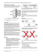
Overview of Hardware
Table 3. Overview of models (hardware)
feature
description
max.
cable
length
order no.
without HMI
with HMI
CLN
X
EH
00
ND1
0
0A
, C
LNXEHSERI
E
S
0
0
ND
CLN
X
EH
S
0
0
ND1
0
0A
CLN
X
EH
14
ND1
0
0A
, C
LNXEHSERI
E
S
1
4
ND
CLN
X
EH
S
1
4
ND1
0
0A
CLN
X
EH
26
ND1
0
0A
, C
LNXEHSERI
E
S
2
6
ND
CLN
X
EH
S
2
6
ND1
0
0A
CLN
X
EH
00
D1
00
A,
C
LN
XE
H
S
E
R
IES0
0D
C
L
NX
E
H
S
00D
10
0A
CLN
X
EH
14
D1
00
A,
C
LN
XE
H
S
E
R
IES1
4D
C
L
NX
E
H
S
14D
10
0A
CLN
X
EH
26
D1
00
A,
C
LN
XE
H
S
E
R
IES2
6D
C
L
NX
E
H
S
26D
10
0A
UI
NTC10kΩ / NTC20kΩ / 0…10 V / slow BI, 0.4 Hz
400 m
0
0
4
4
8
8
0
0
4
4
8
8
NTC10kΩ / NTC20kΩ / 0…10 V fix pull-up / slow BI, 0.4 Hz
400 m
0
0
0
0
2
2
0
0
0
0
2
2
BI
open = 24 V / closed 2.0 mA / totalizer 15 Hz
400 m
0
0
4
4
4
4
0
0
4
4
4
4
AO
0..11 V (max. 1 mA)
400 m
0
0
2
2
4
4
0
0
2
2
4
4
BO
Relay N.O. contact: 3 A, 250 VAC, 30 VDC
400 m
0
0
3
3
4
4
0
0
3
3
4
4
Relay N.O. contact (high in-rush): 10 A, 250 VAC, 30 VDC
400 m
0
0
1
1
1
1
0
0
1
1
1
1
Relay N.O. contact with one common: 3 A, 250 VAC,
30 VDC
400 m
0
0
0
0
3
3
0
0
0
0
3
3
total I/Os
--
0
0 14 14
26 26
0
0 14 14
26 26
bus
interfaces
RS485-1, isolated, BACnet MS/TP, Panel Bus, or Modbus
RTU Master or Slave communication
1)
1200 m
1
2)
1
1
2)
1
1
2)
1
1
2)
1 1
2)
1
1
2)
1
RS485-2, non-isolated, BACnet MS/TP, Panel Bus, or
Modbus RTU Master or Slave communication (NOTE: It is
imperative that the RS485-2 be powered by a power supply
having the proper polarity. Failure to do so will make data
transmission impossible.)
1)
1200 m
1
2)
1
1
2)
1
1
2)
1
1
2)
1 1
2)
1
1
2)
1
Ethernet Interfaces
(
e-mail communication, browser
access, BACnet IP communication, Niagara Network,
Modbus TCP)
100 m
2
2
2
2
2
2
2
2
2
2
2
2
USB 2.0 Device Interface (as Network Interface)
3 m
1
1
1
1
1
1
1
1
1
1
1
1
USB 2.0 Host Interface (max. 200 mA)
3 m
1
1
1
1
1
1
1
1
1
1
1
1
RS232 M-Bus communication via 15-meter-long PW3 /
PW20 / PW60 converters
1)
1000 m
1
1
1
1
1
1
1
1
1
1
1
1
LEDs
power LED (green)
--
1
1
1
1
1
1
1
1
1
1
1
1
status LED (red; indicates an active alarm; is controlled by
Niagara Alarm System; is configurable)
--
1
1
1
1
1
1
1
1
1
1
1
1
LED L1 (yellow; lit = Daemon starting; flashing = station
starting; if L2 is also flashing, then the station has started)
--
1
1
1
1
1
1
1
1
1
1
1
1
LED L2 (yellow; lit = platform has started / is reachable;
flashing = station has started / is reachable)
--
1
1
1
1
1
1
1
1
1
1
1
1
bus status LEDs (for isolated RS485-1 interface)
--
2
2
2
2
2
2
2
2
2
2
2
2
1)
Depending upon bit rate. However, in the case of configuration of RS485-2 for Panel Bus, the communication rate is set to
115.2 kbps, and the max. cable length is hence 800 m.
2)
In the case of these devices, for Panel Bus functionality, an additional license must be purchased (see Table 19).