

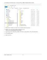


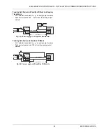


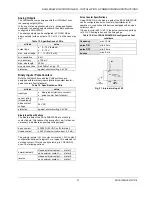


EAGLEHAWK NX CONTROLLER – INSTALLATION & COMMISSIONING INSTRUCTIONS
EN1Z-1039GE51 R1218
24
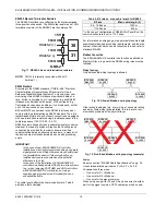
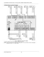
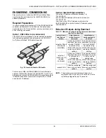
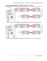
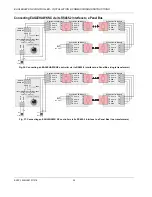
CLNXxxx26xxx Connection Examples
FAN
~
~
1: 24V 0
2: 24V
FAN
~
~
1: 24V 0
2: 24V
TOTALIZER
1: GND
2: SIGNAL
2
1
FAN
1: GND
2: 24V~
FAN
1: 230V N
2: 230V
~
M
M
1
1
2
2
CLNXEH26ND100A
BO1
BO
2
BO3
IN
IN4
BO
4
BO5
IN5
IN
6
BO6
BO7
IN7
IN8
BO8
5
6
7
8
9 10
11 12 13 14 15 16 17 18
AO3
22
AO
2
21
AO1
20
GN
D
19
~
AO
4
23
GN
D1
GN
D2
485-1
+
485-2
+
485-
1-
485-
2-
n.a
.
n.a
.
n.a
.
BI
1
BI
2
BI
3
BI
4
UI
1
UI9
UI
1
0
UI
2
UI
3
UI
4
UI5
UI
6
UI7
24 25 26
27 28 29 30 31 32
33 34 35 36
38 39
40 41 42 43 44 45 46
UI8
47
GN
D
37
DRY
CONTACT
1: GND
2: SIGNAL
2
1
37
/G
ND
37
/G
ND
37
/G
ND
37
/G
ND
1
1
2
2
24V
1: GND (24V 0)
2: 24V POWER
3: 0...10 VDC
~ DRIVE with
0...10V SIGNAL
~
~
2
3
1
M
0...10 VDC
NTC20kOHM
SENSOR
1: GND
2: SIGNAL
1
2
NTC20kOHM
SENSOR
1: GND
2: SIGNAL
1
2
24Vac
ACTIVE SENSOR
1: GND (24V 0)
2: 24V POWER
3: 0...10 VDC
~
~
2
3
1
24
V-
0
24
V~
1
2
L
N
BLOCK 1
BLOCK 2
WARNING
Risk of electric shock or equipment damage!
Low voltage and line voltage must not be wired
within the same block.
!
Fig. 27. CLNXxxx26xxx connection example
For fusing specifications see section "
Fusing
Specifications" on page 20.
NOTE:
Use a min. distance of 10 cm between power cables and 0…10 V / sensor cables in order to prevent signal
disturbances on the 0…10 V / sensor cables.