background image

DESCRIPTIONS

7

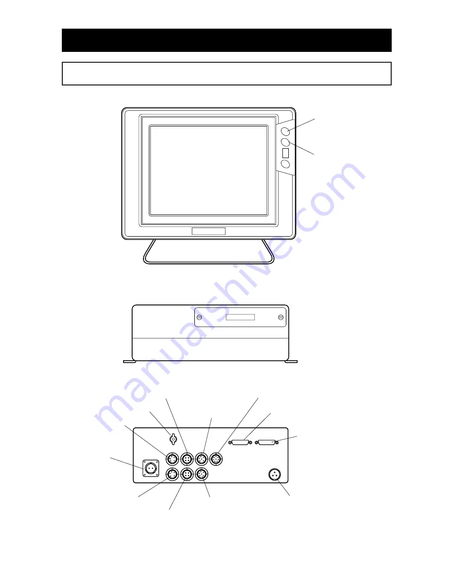
  <Main Unit>   


<Rear of main unit/Connection>

 <Display>

Ground Terminal

To Video Signal 
Cable Display

 To Optional
 Display

To GPS/DGPS 
Antenna    

Remote (4P)  

 Remote for OP display (4P)

DC Power Supply
(2P)

Brightness Key 
(Bright)
(

page 15  )

Brightness Key 
(Dark) 
(


page 15  )

 External Output (6P)

Transducer

5P is used for 50kHz-200kHz

(only HE-6801, HE-6901)


Display Power Supply
(5P)  

OP Display (5P)

  Water Temp. Sensor (8P)


1. MAIN UNIT/DISPLAY

Summary of Contents for HE-6801

Page 1: ......

Page 2: ...ident resulting in the death or serious wound unless you keep the descriptions WARNING Be in danger of incurring the accident resulting in the death or serious wound unless you keep the descriptions CAUTION Be in danger or incurring the slight wound to human or damage to other physical property unless you keep the descriptions Do not reproduce a part or all of contents described on this manual wit...

Page 3: ...THE DISPLAY 11 HOW TO OPERATE MENU 12 BASIC OPERATION POWER ON OFF 14 HOW TO CHANGE FISH FINDER PLOTTER MODE 14 TO CHANGE DISPLAY STYLE PORTRAIT LANDSCAPE 15 TO CONTROL BRIGHTNESS OF SCREEN 15 TO SHOW SIMULATION DISPLAY 16 OPERATION OF PLOTTER HOW TO USE THE CURSOR 18 TO MOVE THE DISPLAY 19 TO ENLARGE REDUCE THE PICTURE 19 TO SELECT THE DISPLAY DIRECTION 21 TO SET RANGE YOU ALWAYS USE 21 TO USE MA...

Page 4: ...O SHOW ISOBATH 45 TO INDICATE PLACE NAME OTHER NAME FISH SHOAL LIGHT HOUSE AND ETC 45 TO SHOW LATITUDE LONGITUDE LINE GRID 46 TO SOUND ARRIVAL ANCHOR WATCH OFF COURSE ALARM 46 OWN BOAT S VECTOR AND COLOR OF OWN BOAT S MARK 47 TO SET READOUT ACCURACY OF EACH INFORMATION 48 TO CHANGE SIZE COLOR AND ETC OF CHARACTERS 48 TO SHOW OWN BOAT POSITION WITH TIME DIFFERENCE OF LORAN C 49 TO SET DGPS BEACON R...

Page 5: ...F WATER TEMP 70 TO SHOW DUAL FREQUENCY DISPLAY 71 TO SET SWEEPING SPEED 71 TO SET AUTO RANGE Automatic Range Control 72 TO SET AUTO SHIFT Automatic Display Range Shift 72 TO SET AUTO GAIN Automatic Sensitivity Control 72 TO SET A MODE 73 TO SET BACKGROUND COLOR 73 TO SET COLOR CONFIGURATION 74 TO SET CLUTTER 74 TO CHANGE UNIT OF DEPTH READOUT 75 TO SET SCALE LINE 75 TO SET SUPER RANGE 75 TO SET WA...

Page 6: ...NG DIAGRAM 84 INSTALLATION OF MAIN UNIT AND DISPLAY 85 MOUNTING THE GPS ANTENNA 86 INSTALLATION OF TRANSDUCER THRU HULL 89 INSTALLATION OF WATER TEMP SENSOR 90 STANDARD COMPOSITION 91 GENERAL INFORMATION OF FISH FINDER 95 TROUBLE SHOOTING 97 SPECIFICATIONS 100 ...

Page 7: ...NG Do not install it in simple method It causes to the accident like human damage Please be sure to install correctly according to descriptions on Installation of the unit of this manual Do not use the information displayed on the screen of unit for navigation directly It causes to the marine disaster Please be sure to use the official marine charts for navigation judgment Do not operate the unit ...

Page 8: ...g firing or electric shock Do not use the damaged cables It causes to firing or electric shock CAUTION Do not pull the cable when you pull out the plug It causes to firing or electric shock because the cable is broken When you pull out the plug be sure to have it in your hand and pull it CAUTION Do not install at the place where rain or spray dashes directly It is not water proof It causes to firi...

Page 9: ...e you ventilate well inside the boat Volatile gas from solvent or etc causes to toxic symptoms When you work using electric tools please keep your hands dry If you hands are wet it causes to electric shock Perfect waterproof treatment should be done when you install the transducer or water temperature sensor through the hull If waterproof is not sufficient it causes to marine disaster because wate...

Page 10: ...d be mounted at the highest position on the boat to maximum satellite reception Obstacles near the antenna will shield it from satellite Then the time of satellite reception will increase or positioning accuracy will become worse 4 HANDLING OF REMOTE DANGER Do not use leaked battery When using wireless remote When leaked liquid stains on body it causes to damage In case of staining wash out with c...

Page 11: ... Important datum like menu contents should be recorded on the notebook etc Take memo of important datum Do not clean the unit with organic solution like thinner alcohol or etc as some parts of the unit and panel are coated or made by plastic In case it is too dirty soak the soft cloth in a synthetic detergent and clean with it after wringing well Prohibited to use the organic solution 6 TFT LCD PA...

Page 12: ...n be used as wireless one if you remove cable Only when wireless remote is used it operates with internal battery It helps to save power consumption Stylish and thin display It can be installed at any place as display is separated from main unit High resolution LCD makes distinct viewing and space saving Many information You can save up to 1 000 points of waypoints up to 24 000 points of event mar...

Page 13: ...To Optional Display To GPS DGPS Antenna Remote 4P Remote for OP display 4P DC Power Supply 2P Brightness Key Bright page 15 Brightness Key Dark page 15 External Output 6P Transducer 5P is used for 50kHz 200kHz only HE 6801 HE 6901 Display Power Supply 5P OP Display 5P Water Temp Sensor 8P 1 MAIN UNIT DISPLAY ...

Page 14: ...5 Adjust sensitivity of left display on dual freq mode SHIFT page 66 Move displayed depth range ZOOM page 67 72 Move expanded area toward sea surface or sea bottom When manual Exp is selected GAIN 1 page64 65 Adjust sensitivity of single freq mode and right display on dual freq mode WAKE COLOR page30 Select color of displayed wake EVENT SHAPE page26 Show event mark on the display WP RECALL page37 ...

Page 15: ...long time take out the batteries When the solution is leaked from battery wipe off the stained solution from case and then put new batteries in 1 2 Screw Battery WARNING Do not use leaked battery When using wireless remote When leaked liquid stains on body it may cause to damage In case of staining wash out with clean water immediately CAUTION Keep at the place where it will not drop due to vibrat...

Page 16: ...direct sun ray on infrared rays sensor of main unit In some case you can not operate the key on remote Take care not to put the obstacles between remote and infrared rays sensor Do not drop it or keep it at the place where there is direct sun ray Handle it carefully ...

Page 17: ...rection from Own Boat to Cursor Depth Measuring Time Bearing Bearing Vector Waypoint Latitude Longitude Cursor Latitude Longitude Differential Mark Only for DGPS Frequency Water Temp 1 WAKE 2 WAYPOINT 3 EVENT MARK 4 ROUTE 5 ALARM 6 READOUT SETTING 7 INFO MODE DISPLAY 8 OTHERS 9 SOUNDER 1 RECALL WAYPOINT 2 CANCEL WAYPOINT 3 ERASE WAYPOINT 4 MEMORIZED COLOR 5 DISPLAY COLORS 6 CHANGE OF SHAPE 7 LIST ...

Page 18: ...Return with MENU key 1 WAKE 2 WAYPOINT 3 EVENT MARK 4 ROUTE 5 ALARM 6 READOUT SETTING 7 INFO MODE DISPLAY 8 OTHERS 9 SOUNDER 1 ERASE 2 MEMORIZED COLOR 3 DISPLAY COLOR 4 CHANGE OF SHAPE 5 LIST EDIT 0 24000 USED Select with RIGHT LEFT key on remote After selection press SET key 1 MEMORIZED COLOR WAKE 12 HOW TO OPERATE MENU How to operate menu You can change contents of item which you set by selectin...

Page 19: ...BASIC OPERATION POWER ON OFF 14 HOW TO CHANGE FISH FINDER PLOTTER MODE 14 TO CHANGE DISPLAY STYLE PORTRAIT LANDSCAPE 15 TO CONTROL BRIGHTNESS OF SCREEN 15 TO SHOW SIMULATION DISPLAY 16 ...

Page 20: ...e datum Note 2 When the engine starts to run battery voltage varies and it may affect to main unit Start the engine after the power of main unit is turned OFF HOW TO CHANGE FISH FINDER PLOTTER MODE Change the display Change by pressing either key S S PL PL for only HE 6801 and HE 6901 S Fish finder mode is shown S PL Plotter mode is shown on left of screen and fish finder mode is shown on right of...

Page 21: ... Dark TO CHANGE DISPLAY STYLE PORTRAIT LANDSCAPE To change display style Portrait Landscape You can change the display landscape portrait landscape reverse and portrait reverse according to the status of installing the unit Select 8 OTHERS 8 INITIAL 6 PICTURE STYLE on menu Select 6 PICTURE STYLE according to the status of installing the unit 1 2 Landscape Portrait Landscape Reverse Portrait Revers...

Page 22: ...TIAL 5 SIMULATION on menu Select item by CENTER key and press SET key OFF Simulation display OFF FIX Own boat is fixed MOVE Own boat moves TO SHOW SIMULATION DISPLAY TO SHOW SIMULATION DISPLAY 1 2 On simulation display DEMO is indicated on the left edge of screen Select OFF to return normal display and press SET key If you indicate cursor when you start simulation display own boat is shown at that...

Page 23: ...LINE 39 TO ERASE LINE 40 TO REGISTER ERASE ROUTE 42 TO RECALL REGISTERED ROUTE SETTING ROUTE NAVIGATION 43 TO ADVANCE WAYPOINT TO RETURN WAYPOINT 44 TO SHOW ISOBATH 45 TO INDICATE PLACE NAME OTHER NAME FISH SHOAL LIGHT HOUSE AND ETC 45 TO SHOW LATITUDE LONGITUDE LINE GRID 46 TO SOUND ARRIVAL ANCHOR WATCH OFF COURSE ALARM 46 OWN BOAT S VECTOR AND COLOR OF OWN BOAT S MARK 47 TO SET READOUT ACCURACY ...

Page 24: ...tude of own boat is not indicated cursor line distance direction and required time from own boat s position to cursor is not shown 1 CURSOR ON OFF key cursor Cursor line own boat mark wake TO MOVE THE CURSOR Indicate the cursor by pressing CURSOR ON OFF key Cursor moves up downward or left right down by turning CENTER key CENETR key CENTER key operates by pushing CENTER key When the cursor is indi...

Page 25: ...en by pressing CENTER key display moves automatically again When map are shown on dual display picture moves to left of map or top of map Picture can not move to right of map or down of map 1 2 CURSOR ON OFF key CENTER key TO ENLARGE REDUCE THE PICTURE Enlargement and reducing the display Expansion Reduction of display When the cursor is indicated display expands reduces at center of cursor s posi...

Page 26: ... Display reduces by pressing RED key Map corresponded to scale range encircled by rectangle expands or reduces Each time when you press key map to be expand reduced switches Range Scale Scale Range for right map Scale Range for left map Scale range when maps are shown side by side Left map can be expanded or reduced on figure Scale range when maps are shown up and down Upper map can be expanded or...

Page 27: ...range You can set up to 2 ranges You change range by pressing key Select 8 OTHERS 3 SWITCH KEY on menu Establish each items on 3 SWITCH KEY page 57 Each time you press key range switches alternately 1 2 3 QUICK RANGE key Note It is effective when 6 READOUT SETTING 1 MAP READOUT 8 TWIN MAP is OFF Course Up Manual Auto course up can be selected on menu Refer to page 54 Auto course up ON When the bea...

Page 28: ... is given to map card in upper slot Map Card Upper Lower Cover Inserting Card Insert card into slot while sticker side faces up Be sure to face sticker side of map card memory card up Unless it they are not shown on the screen Take care of facing sticker side up when inserting card Wrong insertion causes to failure Sticker ...

Page 29: ...MORY CARD on the menu and operate each items page 57 After finished above procedure 4 it returns to normal display Then turn the power of unit OFF and pull out memory card from slot Finally put the cover for card slot 1 2 3 4 5 Note 1 When you insert take off memory card be sure to the power of unit OFF Note 2 Storage of datum in this unit or memory card is not guaranteed to keep permanently Impor...

Page 30: ...ey Red letter item indicates that item s data is stored in card If data is not stored in card copy is completed When data is stored in card Select rewrite or cancel copy by SET key or CLR key When rewriting is executed previous data is deleted 1 2 3 4 STORE FROM UNIT TO CARD BLOCK NUMBER OF STORED CARD RED USE WHITE UNUSED 0 1 2 3 4 5 6 7 8 9 1 WAKE 2 WAYPOINT 3 EVENT MARK 4 DRAW LINE 5 ROUTE 6 AL...

Page 31: ...ter item indicates that item s data is stored in card If data is not stored in unit copy is completed When data is stored in unit Select item on below figure by SET key or NUMBER key 1 2 3 4 READ FROM CARD TO UNIT BLOCK NUMBER OF STORED CARD RED USE WHITE UNUSED 0 1 2 3 4 5 6 7 8 9 1 WAKE 2 WAYPOINT 3 EVENT MARK 4 DRAW LINE 5 ROUTE 6 ALL DATA RED USED COPY BY SET KEY READ WAKE TO UNIT DATA IS IN C...

Page 32: ...h school shoals or etc at any option Shape 8 types selected on the menu Color Selected among red yellow green magenta white cyan blue and color of wake Numbers of point Up to 24 000 points can be entered on the display Combination of shape and color is free Event Mark will be shown when the range of map enlarges less than 50NM When it s range reduce more than 80NM all event marks will be shown by ...

Page 33: ...lease refer to HOW TO OPERATE MENU page12 for operation of menu To erase all event marks All event marks are erased Select 3 EVENT MARK 1 ERASE 3 ERASE ALL on the menu All event marks are erased by pressing SET key 1 2 SET key To erase the event mark by shape All event marks which have selected by each shape are erased Select 3 EVENT MARK 1 ERASE 2 ERASE BY SHAPE on the menu Select and designate s...

Page 34: ... OPERATE MENU page12 for operation of menu Note 1 When unit is delivered from factory 3 EVENT MARK 1 ERASE 4 ERASE BY CURSOR on the menu is set to OFF page 53 Set ERASE BY CURSOR ON to operate this function TO EDIT EVENT MARK To edit event mark You can edit shape color latitude and longitude at every event mark manually You can also enter comment name 1 Indicated List Select 3 EVENT MARK 5 LIST ED...

Page 35: ...of event number before change is not revised e e h h h h h h e e e e e e e e e e e e e e e e e e e e e e e e e e e e e e e e e e e e e e e e e e e e e e e e e e e e e e e e e e e e e e e e e e e e e e e e e e e e e e e e e e e e e e e e e e e e e e e e e e e e e e e e e e e e e e e e e e e e e e e e e e e e e e e e e e e e e e e e e e e e e e e e e e e e e e e e e e e e e e e e e e e e e e e e e e...

Page 36: ...aypoint Mark Wake Track which own boat moved is called Wake When wake is shown wake is continued to record When wake is not shown it s recording is interrupted Memory interval of wake Wake is continuous connected lines between each memorized own boat s position at certain interval The memory interval is called Memory interval of wake There are advantages and disadvantages respectively in long inte...

Page 37: ...There is upper limit of wake which you can record Maximum numbers of point which you can store is 32 000 points When wake points exceed 32 000 points wake from the oldest is erased When you sail for a long time distance it is recommended to set the memory interval to long Please refer to HOW TO OPERATE MENU page12 for operation of menu To erase all wakes All wakes are erased Select 1 WAKE 4 ERASIN...

Page 38: ...sily is starting point terminal point and sharp corner of wake Note 1 When unit is delivered from factory 1 WAKE 4 ERASING WAKES 2 ERASE BY CURSOR is set to OFF page 52 Set ERASE BY CURSOR to ON to execute this function Point Be sure to stack cursor on point Cursor Even if cursor is stacked on between 2 points wake is not erased Cursor Point By pressing CLR key display to confirm erase is shown On...

Page 39: ...ypoint mark will be shown when map range enlarges more than 50NM In case it s range reduces less than 80NM all waypoints will be shown by dots Input of Comment Name You can add Comment Name at each waypoint mark page 35 When waypoint mark is shown by dot Comment Name is not shown 1 2 3 4 5 6 7 8 Press WP SAVE key Waypoint mark and waypoint number are shown They are indicated at cursor s position w...

Page 40: ...efer to HOW TO OPERATE MENU page12 for operation of menu To erase all waypoint marks All waypoint marks are erased Select 2 WAYPOINT 3 ERASE WAYPOINT 2 ERASE ALL on the menu All waypoint marks are erased by pressing SET key 1 2 SET key To erase waypoint mark by shape All waypoint marks which have selected by each shape are erased Select 2 WAYPOINT 3 ERASE WAYPOINT 2 ERASE BY SHAPE on the menu Sele...

Page 41: ...E MENU page12 for operation of menu Note 1 When unit is delivered from factory 2 WAYPOINT 3 ERASE 4 ERASE BY CURSOR is set to OFF page 52 Set ERASE BY CURSOR to ON to execute this function TO EDIT WAYPOINT MARK To edit waypoint mark You can edit shape color latitude and longitude at every waypoint mark manually You can also enter comment name 1 Indicated List Select 2 WAYPOINT 7 LIST EDIT by press...

Page 42: ...point number before change is not revised e e h h h h h h e e e e e e e e e e e e e e e e e e e e e e e e e e e e e e e e e e e e e e e e e e e e e e e e e e e e e e e e e e e e e e e e e e e e e e e e e e e e e e e e e e e e e e e e e e e e e e e e e e e e e e e e e e e e e e e e e e e e e e e e e e e e e e e e e e e e e e e e e e e e e e e e e e e e e e e e e e e e e e e e e e e e e e e e e e e ...

Page 43: ...aypoint mark instead of By pressing SET key waypoint navigation is set 1 2 3 Note Following conditions are necessary when you set the waypoint navigation Latitude Longitude of own boat s position should be shown on the screen Waypoint should have been already set SET key WP RECALL key NUMBER key 37 WP SAVE key Setting of Simple Waypoint Navigation By pressing CURSOR ON OFF key cursor is indicated ...

Page 44: ...38 TO CLEAR WAYPOINT NAVIGATION Cancellation of waypoint navigation Press WP RECALL key By pressing CLR key waypoint navigation is canceled 1 2 CLR key WP RECALL key ...

Page 45: ...When you finish to draw line press CLR key CURSOR ON OFF key Starting point Terminal point Intermediate point Line 1 2 3 4 5 Distance between two points When line is drawn distance from a previous position point to Cursor position is indicated You can know the distance between any two points Color of line Each time when you press WAKE COLOR key color changes Color can be confirmed by color of SCAL...

Page 46: ...or operation of menu To erase all lines All lines are erased Select 8 OTHERS 1 DRAW LINE 4 ERASE LINE 1 ERASE BY COLOR on the menu Select ERASE ALL by turning CENTER key left rightward All lines are erased by pressing SET key 1 2 3 SET key Erase line by cursor By stacking cursor on line erase line respectively It is necessary to make effective of function ERASE BY CURSOR on the menu beforehand in ...

Page 47: ...stacked on intermediate point Erase the line to previous intermediate point or starting point if there is no previous intermediate point and the line to next intermediate point or terminal point if there is no intermediate point When cursor is stacked on terminal point Erase the line to previous intermediate point or starting point if there is no previous intermediate point 41 By pressing CURSOR O...

Page 48: ...ter Route number with NUMBER key and press SET key A route number in red color can not be used because it has already been registered Use other number white or erase the route you don t need Stack cursor on intermediate point course change point with CENTER key and press SET key Designate next intermediate points repeatedly mark is indicated on each intermediate point and they are connected in lin...

Page 49: ...the same time own boat is connected with next intermediate point course change point as waypoint line 2 If it is judged that own boat passes the intermediate point course change point and it goes to the intermediate point course change point then waypoint line connects between own boat s position and intermediate point course change point 3 Until own boat passes the last intermediate point course ...

Page 50: ...UTE 5 ADVANCE WAYPOINT on the menu Each time when you press SET key waypoint line is switched to next intermediate point Each time when you press SET key on display 4 ROUTE 6 RETURN WAYPOINT waypoint line is switched to previous intermediate point 1 2 3 SET key Own boat Own boat Waypoint line Route Advance waypoint Advance waypoint Waypoint line Waypoint line Waypoint line Route Return waypoint Re...

Page 51: ... TO INDICATE PLACE NAME OTHER NAME FISH SHOAL LIGHT HOUSE AND ETC To indicate place name other name fish shoal light house and etc Select 6 READOUT SETTING 1 MAP READOUT 4 POINT NAME on the menu SET each item of 4 POINT NAME After you finish menu adjust range with EXP key RED key or key and then indicate place name other name fish shoal lighthouse and etc QUICK RANGE key RED key EXP key Display co...

Page 52: ...of alarm setting are available Arrival alarm When own boat enters within a specified distance circle from it s waypoint or route point alarm sounds Anchor watch alarm When own boat drifts beyond specified distance circle from it s waypoint or route point alarm sounds Arrival alarm Waypoint Alarm sounds Set value Anchor alarm Alarm marker Waypoint Alarm sounds Set value Alarm marker Off course alar...

Page 53: ...t navigation is set When the power key is pressed OFF it is canceled 1 2 Please refer to HOW TO OPERATE MENU page12 for operation of menu Please refer to OPERATION OF FISH FINDER page 69 70 for Water temp alarm Fish alarm and Depth alarm OWN BOAT S VECTOR AND COLOR OF OWN BOAT S MARK Own boat s vector and color of own boat s mark Own boat s vector It indicates own boat s course But it does not ind...

Page 54: ...1 1 accuracy 1 10 accuracy 1 2 CENTER key TO CHANGE SIZE COLOR AND ETC OF CHARACTERS To change size color and etc of characters You can change attribute size and color of informational characters information like latitude longitude etc Example Change the attribute of character relating to own boat Select 6 READOUT SETTING 5 DISPLAY LETTERS 5 OWN BOAT LETTER 1 LAT LON LETTER on the menu Select and ...

Page 55: ...f Loran C Loran C Loran C Long Range Navigation is hyperbolic navigation system using long wave band Theory of locus of point that difference of arrival time of signal transmitted from two stations is constant value conforms to hyperbola focused at those stations This hyperbola is called Line of position LOP and intersection point of more than two LOPs will be position of observatory One chain com...

Page 56: ...iver User Beacon Receiver TO SHOW DUAL DISPLAY OF MAP To show dual display of map Select 6 READOUT SETTING 1 MAP READOUT 8 TWIN MAP on the menu Select either of below items with CENTER key OFF Single map display LEFT RIGHT Dual map display divided side by side UPPER LOWER Dual map display divided top and bottom In case of dual map display you can switch to expansion or reduction mode with key Disp...

Page 57: ...o plotter key When display is plotter mode it is effective When display is plotter mode you can allocate fish finder key on remote to plotter key 1 2 Event Mark Event Mark Make distance marker large Make distance marker small Event Mark Event Mark Event Mark Event Mark Event Mark Event Mark When it is allocated to plotter key fish finder keys on below figure can be used for plotter key Please refe...

Page 58: ...lect by turning CENTER key left rightward ON ERASE OFF NOT ERASE Select whether memory interval is done by TIME or DISTANCE Select by CENTER key left rightward Set the interval of Memory interval which is done by TIME Set by turning CENTER key left rightward page 30 20 sec Set the interval of Memory interval which is done by DISTANCE Set by turning CENTER key left rightward page 30 0 05NM km When ...

Page 59: ...o use when you enter event mark Select by turning WAKE COLOR Select whether indicated or not indicated on each color for recorded waypoint marks Select by turning CENTER key left rightward ON INDICATED OFF NOT INDICATED ALL Indicate all colors Not indicate all colors Select shape of event mark from 8 kinds Show the list of information for entered event mark and change content Changeable items Mark...

Page 60: ...nd which you paint full COASTLINE COLOR Designate coastline color COLOR OF SEA Blue Less than 1000m Dark Blue 1 more than 1000m Dark Blue 2 Select isobath you use and then set whether it is indicated or not ON Indicate OFF Not indicate Show isobath list When range is enlarged than set range with EXP key etc isobath is shown 10 Designate whether POINT NAME W GREEN LIGHTHOUSE BUOY 5 FISH HAVEN 1 COU...

Page 61: ... Set Loran C chain page 49 8930 Set slave station of Loran C page 49 30 Set slave station of Loran C page 49 50 Set slave corrected value for slave station of Loran C page 49 0 00 Set slave corrected value for slave station of Loran C page 49 0 00 Designate type of own boat s mark Designate whether own boat s bearing is indicated or not page 47 OFF Not indicate SHORT Indicate with short line LONG ...

Page 62: ...ndicate up to 1 1 accuracy 1 10 Indicate up to 1 10 accuracy Designate size color indicate or not indicate of latitude longitude boat speed bearing and measured time L M S Designate size of character ALL L OFF Not indicate COLOR Indicate in designated color ALL WHITE YELLOW for measured time Designate size color indicate or not indicate of l a t i t u d e l o n g i t u d e d i s t a n c e b e a r ...

Page 63: ... designated Erase all lines Set whether line can be erased by cursor or not Select by turning CENTER key left rightward ON ERASE OFF NOT ERASE Initialize memory card Store information set in main unit into memory card page 24 Reading information stored in memory card into main unit page 25 Set range display value 2 kinds Range 1 Range 2 Each time when you press RANGE CHANGE key Range 1 0 1NM km an...

Page 64: ...osition Designate whether own boat position is corrected or not OFF not correct ON correct Designate corrected value of latitude Select with CENTER key left rightwards 0 00 Designate corrected value of longitude Select with CENTER key left rightwards 0 00 Set corrected value of above 2 3 to 0 Move own boat mark to cursor position Designate corrected value of water temp Select with CENTER key left ...

Page 65: ...display mode page 14 ON Fish finder operates at PL display mode Select whether waypoint mark comment entered on menu 2 WAYPOINT 7 LIST EDIT is indicated on map or not ON Select whether event mark comment entered on menu3 EVENT MARK 5 LIST EDIT is indicated on map or not ON Set readout density of place name indicated on map NORMAL MANY Allocate fish finder key on remote to plotter key when display ...

Page 66: ...MEMO 60 ...

Page 67: ...TO SET SWEEPING SPEED 71 TO SET AUTO RANGE Automatic Range Control 72 TO SET AUTO SHIFT Automatic Display Range Shift 72 TO SET AUTO GAIN Automatic Sensitivity Control 72 TO SET A MODE 73 TO SET BACKGROUND COLOR 73 TO SET COLOR CONFIGURATION 74 TO SET CLUTTER 74 TO CHANGE UNIT OF DEPTH READOUT 75 TO SET SCALE LINE 75 TO SET SUPER RANGE 75 TO SET WATER TEMP GRAPH 76 TO SET AUTO RANGE MAX DEPTH 76 T...

Page 68: ...der display In case of showing fish finder display only Frequency Indication When unit is single frequency version No indication When unit is dual frequency version L Low freq H High freq However in case of parallel display of dual frequency position where Frequency is indicated changes Refer to TO SHOW DUAL FREQUENCY MODE page 71 Water Temp Indication It is indicated when optional water temp sens...

Page 69: ...e depth display range Each time when you press RANGE S key the depth decreases To increase the depth display range Each time when you press RANGE D key the depth increases 1 RANGE key Depth Display Range 5 8 10 15 20 30 40 50 60 80 100 125 150 180 200 250 300 400 500 600 800 1000 1500 2000m 0 200 kHz 50 200 kHz 50 200 kHz 300W 32 40kHz 28kHz 50kHz 40 75kHz 85 90kHz 36 65kHz 50 55 kHz ...

Page 70: ...ttom is called the second reflection Normally it s second reflection is shown on the twice depth of the actual bottom first reflection To decrease sensitivity Each time when you press GAIN1 L key gain bar becomes short and the sensitivity decreases To increase sensitivity Each time when you press GAIN1 H key gain bar becomes long and the sensitivity increases 1 GAIN1 key This describes operation f...

Page 71: ...ar becomes short and the sensitivity decreases To increase sensitivity Each time when you press GAIN1 H key gain bar becomes long and the sensitivity increases 1 2 GAIN1 key GAIN2 key In case of dual frequency display you can change the sensitivity on right side of screen by GAIN1 key and the sensitivity on left side of screen by GAIN2 key H L In case of Low High Sensitivity Too poor sensitivity A...

Page 72: ...display range becomes to 10 18m Even if image you want to see is small it is enlarged by setting the depth display range to shallow range when shift is selected To shift to shallow depth Each time when you press SHIFT S key the display range becomes shallow To shift to deep depth Each time when you press SHIFT D key the display range becomes deep 1 Shift Shift of display range SHIFT key 8m 8m 0 0 ...

Page 73: ...xpansion display set 1 EXP MODE to OFF page 68 70 You can move and see expanded area to top or bottom of display You can not operate ZOOM key except for manual expansion mode Expansion rate is selected among 2 times 4 times and 8 times Expansion Rate page 68 Expansion rate is set to 4 times when the unit is delivered from factory Displayed range varies depending on Expansion Rate Please refer to T...

Page 74: ...and return to normal display BOTTOM LOCK Bottom contour is indicated as a straight line and expansion view of certain area from it s contour is shown AUTO EXPANSION Expanded display up or down in the center of bottom MANUAL EXPANSION Expanded display up or down in the center of optional position You can move expanded area by ZOOM key as you wish Displayed range varies depending on Expansion Rate E...

Page 75: ...TEMP SET1 3 TEMP SET2 on menu Water Temp Alarm Alarm goes off within or out of two water temperatures TEMP SET 1 TEMP SET 2 Water temp sensor is required for this function 1 2 3 Water Temp Alarm Example In case of TEMP SET 1 5 TEMP SET 2 10 10 5 0 Out Range Out Range In Range Select 5 ALARM 4 FISH ALARM 1 ALARM SET on menu Establish 1 ALARM SET S Sensitivity increases to catch the response from sm...

Page 76: ...s and depth readout flashes OFF Depth alarm is canceled Select DEPTH SET1 or DEPTH SET2 Depth Alarm Alarm goes off within or out of two depths DEPTH SET 1 DEPTH SET 2 1 2 3 Depth Alarm Example Depth 10m DEPTH SET 1 In Range Alarm Alarm Alarm Out of range Out of range Depth 15m DEPTH SET 2 Select 8 OTHERS 6 CORRECTION 5 TEMP CORRECT 1 TEMP CORRECT on menu Establish 1 TEMP CORRECT When water temp re...

Page 77: ...g the sweeping speed Relation of sounding rates and sweeping speed 5 sweeping speed can be selected on the menu Ratio of sweeping speed vs sounding rates at each speed is shown on the below table 1 2 Sweeping Speed Sweeping Speed Sounding Rates 1 1 1 2 1 4 1 8 FREEZE Fast Slow Select 9 SOUNDER 1 DISPLAY on menu Establish 1 DISPLAY 1 LOW Low frequency image is displayed on whole screen 2 HIGH High ...

Page 78: ...nu Set 3 AUTO RANGE to SHIFT Displayed range is automatically changed shifted so that sea bottom is always shown on the optimum position of screen lower half area 1 2 Auto Shift TO SET AUTO GAIN Automatic Sensitivity Control Select 9 SOUNDER 4 AUTO GAIN on menu Establish 4 AUTO GAIN LOW Sensitivity decreases When you judge status of bottom it helps you to confirm second or third reflection HIGH Se...

Page 79: ... differs from surrounding brightness It becomes easy to see the display by selecting the background color among three colors 1 2 Background Color Select 9 SOUNDER 6 A MODE on menu Establish 6 A MODE ON A mode is indicated OFF A mode is not indicated It is displayed on the right side of screen between fish finder display and depth calibration and it s width changes according to strength of reflecte...

Page 80: ...se by displayed color As display of response varies by changing color configuration it enables to display defined color specially 1 2 Color Configuration Please refer to HOW TO OPERATE MENU page12 for operation of menu TO SET CLUTTER Select 9 FISH FINDER 7 COLOR SET 3 CLUTTER on menu Set 3 CLUTTER 13 ranks 0 12 Fish school or bottom is displayed while the strength of reflected echo is corresponded...

Page 81: ...Select 9 SOUNDER 8 OTHERS 2 SCALE LINE on menu Set 2 SCALE LINE ON Indicated OFF Not indicated Horizontal dot lines are shown at the position of depth scale on the screen 1 2 Scale Line TO SET SUPER RANGE Select 9 SOUNDER 8 OTHERS 3 SUPER RANGE on menu Set 3 SUPER RANGE ON Rewrite previous image OFF Super Range function is canceled When depth range displayed depth range changes it rewrites whole p...

Page 82: ...E MAX DEPTH Select 8 OTHERS 6 SPECIAL SETUP 1 AUTO RANGE MAX on menu Set 1 AUTO RANGE MAX 30m 50m 100m 200m 300m Max Depth It sets Maximum Depth when Auto Range is operated 1 2 Auto Range Max Depth TO SET CLEAN ECHO Select 9 SOUNDER 8 OTHERS 6 SPECIAL SETUP 2 CLEAN ECHO on menu Set 2 CLEAN ECHO ON Used OFF Canceled Compared previous reflected signal with current reflected signal the weakest reflec...

Page 83: ... When STC is set to ON sensitivity near sea surface decreases When you increases sensitivity for shallow water set STC to OFF 1 2 STC TO SET TRANSMITTING OUTPUT Select 9 SOUNDER 8 OTHERS 5 SPECIAL SETUP 4 OUTPUT POWER on menu Set 4 OUTPUT POWER HIGH LOW 2 ranks of transmitting output Low or High can be selected except for 50 200kHz 300W 1 2 Transmitting Output Please refer to HOW TO OPERATE MENU p...

Page 84: ...sensitivity automatically LOW Keep sensitivity low HIGH Keep sensitivity high OFF Not used Enlarge display BOTTOM LOCK Bottom contour is indicated as a straight line and expansion view of certain area from it s contour is shown AUTO EXP Enlarge up or down in the center of bottom MANUAL EXP Enlarge up or down in the center of optional position OFF Cancel expansion mode Set expansion rate when expan...

Page 85: ...t factory setting Indicate water temp graph Water temp sensor is option ON Indicated OFF Not indicated Set Maximum depth of Auto Range 30m 50m 100m 200m 300m Max Depth Show clear display less noise ON Used OFF Not used Eliminate reflection like plankton and air bubble WEAK MEDIUM STRONG OFF Canceled Switch transmitting output HIGH LOW ...

Page 86: ...80 MEMO ...

Page 87: ...NG DIAGRAM 84 INSTALLATION OF MAIN UNIT AND DISPLAY 85 MOUNTING THE GPS ANTENNA 86 INSTALLATION OF TRANSDUCER THRU HULL 89 INSTALLATION OF WATER TEMP SENSOR 90 STANDARD COMPOSITION 91 GENERAL INFORMATION OF FISH FINDER 95 TROUBLE SHOOTING 97 SPECIFICATIONS 100 ...

Page 88: ...NSIONAL DRAWING 82 298 256 59 23 31 280 206 170 57 310 120 29 25 262 227 100 222 193 92 Display Main Unit is dimensions for HE 6801 HE 6802 140 57 Drawing of holes for installing the bracket 170 37 Unit mm ...

Page 89: ...on Video Signal Cable GPS Receiver or DGPS Receiver Battery 11 35V DC White Black Power Supply Cable NMEA Equipment Display Option Remote for Display 4P Option Transducer φ25 3P only HE 6801 HE 6901 5P for 50kHz 200kHz Power Supply for Display 5P Option Transom Water Temp Sensor Option ...

Page 90: ...ifferential beacon receiver GPS Receiver or Differential Beacon Receiver Connector for Input Output Main Unit Data Output Power Supply for External Equipment DC Power Supply Data Format Transmission Data Transmission Format NMEA0183 GGA GLL VTG 4800 bps Start bit 1 Data bit 8 Parity bit nil Stop bit 1 ...

Page 91: ...e Procedure of installing display When you use portrait display change direction of bracket to fit portrait 1 Decision of place you install While the bracket is mounted with display you decide the place you install and put the mark Keep enough space behind the display to connect with cables 2 Installation of bracket Install the bracket with supplied screws into four outside holes Face two open sid...

Page 92: ... ANTENNA 1 In case of using turnable DGPS antenna stand Procedure of mounting 1 Connection of antenna and turnable antenna stand 1 Pull out cable from aluminum base to mount turnable antenna stand into GSP receiver or DGPS receiver 2 Rotate clockwise and mount turnable antenna stand into aluminum base of GSP receiver or DGPS receiver Do not grasp joint between redome and aluminum base 3 Fix cable ...

Page 93: ... connect screw adapter with GPS receiver or DGPS receiver 2 Connect screw adapter with aluminum base of GPS receiver or DGPS receiver Grasp aluminum base and turn it clockwise on below figure Do not grasp joint between redome and aluminum base Joint Do not put the power on joint Grasp base and turn 4 Connect extension cable with cable of GPS receiver or DGPS receiver Wind joint with self melt tape...

Page 94: ...al Then the time of satellite reception will decrease or positioning accuracy will become worse Condition of position to be installed 1 Choose a position away from all metal accessories 2 Mount at least 4 meters away from medium short wave high voltage transmitting antenna 3 Mount outside of radar s cone Vertical beam width 30 40 4 Mount at least 5 meters away from INMARSAT antenna 5 Mount at leas...

Page 95: ...tools please keep your hands dry If you hands are wet it causes to electric shock Do not install on the aluminum boat It may cause to corrosion DANGER WARNING Installation of transducer Thru hull 1 Make an approx φ25 hole on the bottom Do not install on the aluminum boat It may cause to corrosion 2 Insert screw of transducer into hole and fix with one cork packing one washer and one nut Another on...

Page 96: ...ill occur When you work using electric tools please keep your hands dry It causes to electric shock Water Temp Sensor Cork Packing Nut 2 pcs Washer Rubber Packing Installation of Thru hull Water Temp sensor 15m TC02C Water Temp Sensor Hull Gland for Water Temp Sensor TC02CS TCK01 Put the seal for waterproof at joint point It can be installed on FRP boat Do not install on the aluminum boat It may c...

Page 97: ...ain Unit Mush room Tapping Screw for Display Power Supply Cable for Display 5P 5P 3m M6x20 SUSx 4 pcs M5x20 SUSx 4 pcs Cable for Remote 4P 4P 3m Bracket x 1pce Clamping Knob x 2 pcs Rubber Ring x 2 p cs Washer x 2 pcs Power Supply Cable Cable Cover M4x16 SUS Pan head Tapping Screw x 2 ...

Page 98: ...92 Brand Plate Operation Manual Transducer Only HE 6801 HE 6901 Map Card ...

Page 99: ...93 GPS Antenna Extension Cable Self melted tape Screw Adapter Turnable Antenna Stand AD01 Clamp Band Round plane tapping screw x 4 15m In case of HE 6801 HE 6901GP HE 6802 HE 6902GP ...

Page 100: ...94 DGPS Antenna Extension Cable Self melted tape Screw Adapter Turnable Antenna Stand AD01 Clamp Band Round plane tapping screw x 4 In case of HE 6801 HE 6901DGP HE 6802 HE 6902DGP 15m ...

Page 101: ...r and reception to transducer Round trip 1 sec Round Trip 0 5 sec Reflected wave from fishschool Reflected wave from sea bottom Transducer For example in case of roundtrip time between transmission and reception is 1 sec to sea bottom Roundtrip distance 1500m sec X 1sec 1500m Actually it s half is depth Depth 1500m 2 750m In case of roundtrip time between transmission and reception is 0 5 sec to f...

Page 102: ...ink the larger fish school on the screen the most fish volume But when fish school are located at the shallow depth and the deep depth fish school at the deep depth is displayed bigger than at the shallow depth Because the transmitted wave spreads wider as it goes deeper and the reflected wave spreads wider as it goes shallower As this result the deeper becomes the wider the width of fish school b...

Page 103: ...de of own boat are not indicated Waypoint is not set Latitude longitude of own boat are not indicated Route is not set Remedy Recharge the battery Tighten firmly Clean and remove the rust dust etc In case of corrosion please replace Replace the power supply cable Replace the connector Check the polarity and connect correctly Replace with new power cable Ask to repair Adjust the brightness control ...

Page 104: ...ransducer where it is always immersed under the waterline Supplement liquid so that transducer can be immersed into water Install the transducer where it is always immersed under the waterline Check the installation of transducer Move the own boat or wait air bubbles disappear Increase the sensitivity Or set to Auto Gain automatic sensitivity control Remove the attachment well Remove the stain fro...

Page 105: ...oat s fish finder Noise from engine Decrease the sensitivity Or set to Auto Gain automatic sensitivity control Noise disappears if the adequate distance between own boat and other keeps Change the routing of cables such as transducer cable power supply cable or etc Separate from engine as far as possible ...

Page 106: ...ing to Cursor Isobath Full Paint Map Data HE 6801 HE 6802 8 4 inch TFT color LCD HE 6901 HE 6902 10 4 inch TFT color LCD Portrait Landscape 640 x 480 11 35VDC 100 H X 310 W X 220 D mm HE 6801 HE 6802 227 H X256 W X113 D HE 6901 HE 6902 262 H X 298 W X 113 D mm HE 6801 HE 6802 1 6Kg Display 3 5Kg Main Unit HE 6901 HE 6902 2 2Kg Display 3 5kg Main Unit Mercator Projection 0 005 500NM 5 sec 10 sec 20...

Page 107: ...epends on freq 0 2 000 m depends on freq OFF Range Shift OFF Low High OFF ON OFF Small Large OFF Within Range Out of Range OFF Within Range Out of Range OFF Bottom Lock Auto Exp Manual Exp X2 X4 X8 4 steps plus freeze 3 colors Black Blue and White 8 colors Brown Red Yellow Green Magenta White Cyan and Blue Meter Feet Fathoms Brazas OFF ON OFF ON OFF Weak Medium Strong Low High except for 300W DGPS...

Page 108: ......

Reviews:

Related manuals for HE-6801