2
Shadows cast by neighbouring walls, trees and roof
overhangs should also be avoided. In practice, the Solar
Panel should be positioned a minimum of twice the width
of the eaves overhang, below the eaves where is
reachable to sun exposure. Remember that in winter the
sun is lower in the sky and you should avoid winter
shadows where possible.
2. Detecting sensitivity: A passive infrared sensor operates by
detecting the objective movement and heat. When the
temperature of the moving object and its surrounding area
are close in value, it may reduce PIR’s sensitivity. The
motion detector’s infrared beams radiate outward like the
slat of a wooden fence. Prior to mounting, keep in mind
that the motion sensor is more sensitive to the motion that
crosses these “slats”, and less sensitive to the motion that
moves directly towards the sensor.
3. Mounting height: For best results, mount the camera 2m
above the ground. Select an appropriate location where
the camera can clearly be seen and detect for best viewing
effect.
4. Rechargeable battery
A high capacity 6V 1.2Ah sealed lead acid rechargeable
battery ensures that the Solar Panel is self maintainable
during darkness and long winter periods.
5. Initial power-up battery
An Alkaline 9V PP3 battery is supplied in the PIR Camera
to provide the initial power to the system.
6. Infrared LEDs for improved night vision
When PIR Camera is activated during nighttime, 6 infrared
LEDs adjacent to the lens is of great help to enhance
nighttime visibility.
7. Reset button
When PIR Camera is not working properly, press the reset
button for recovery.
Installation
Step 1: Install the PIR camera
1. Use the fixing template provided to mark the position of the
two fixing holes. Drill two holes with 25mm in depth and
5mm in width by inserting the plastic wall plugs supplied.
2. Lead either the jack of solar connecting wire or the jack of
DC power cord through the rubber gasket on the backplate,
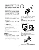
leaving 15cm length of wire inside the backplate. (FIGURE
1)
74mm
cm
FIGURE 1
Note:
If only a PIR Camera (VC401) is used, adopt the DC
power cord for connection. If a whole system (VC401) is
used, adopt the solar connecting wire for connection.
3. Screw the backplate to the wall using the fixing screws
provided.
4. Adjust the channel switch, enabling its channel to be the
same as that of the Receiver, such as Universal Receiver
(VR111) or Wireless USB Receiver (VR131).
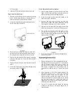
5. Connect the connector of rechargeable battery wire to the
wire of battery jack. (FIGURE 2)
FIGURE 2
6. Plug either the jack of solar connecting wire or the jack of
DC power cord to the camera’s jack socket.
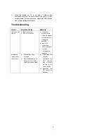
7. Refit the camera to the backplate using two fixing screws
provided. (FIGURE 3)
FIGURE 3
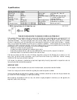
8. The PIR Camera can be swiveled downward to 50° and


