


Rev. 1.00
36
��ne 1�� �01�
Rev. 1.00
37
��ne 1�� �01�
HT46R003B
Cost-Effective A/D 8-bit OTP MCU
HT46R003B
Cost-Effective A/D 8-bit OTP MCU
Bit 3
TEG
: Timer/Event Counter active edge selection
In event counter mode (TM1~TM0 = 01)
0: Count on rising edge
1: Count on falling edge
In pulse width measurement mode (TM1~TM0 = 11)
0: Start counting on falling edge, stop on the rising edge
1: Start counting on rising edge, stop on the falling edge
Bit 2~0
TPSC2~ TPSC0
: Timer prescalar rate selection
000:
f
S
001:
f
S
/2
010:
f
S
/4
011:
f
S
/8
100:
f
S
/16
101:
f
S
/32
110:
f
S
/64
111:
f
S
/128
Timer Mode
In this mode, the Timer/Event Counter can be utilized to measure fixed time intervals, providing
an internal interrupt signal each time the Timer/Event Counter overflows. To operate in this mode,
the Operating Mode Select bit pair, TnM1/TnM0, in the Timer Control Register must be set to the
correct value as shown.
Bit7
Bit6
1
0
Control Register Operating Mode Select Bits for the Timer Mode
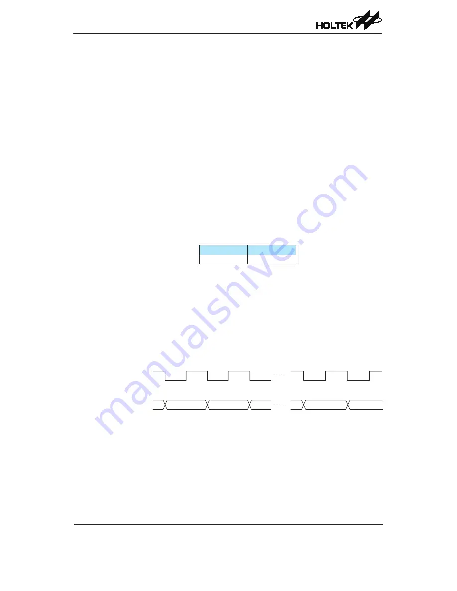
In this mode the internal clock is used as the timer clock. The timer input clock source is f
SYS
, f
SYS
/4
or f
LIRC
. However, this timer clock source is further divided by a prescaler, the value of which is
determined by the bits TPSC2~TPSC0 in the Timer Control Register. The timer-on bit, TON must
be set high to enable the timer to run. Each time an internal clock high to low transition occurs,
the timer increments by one. When the timer is full and overflows, an interrupt signal is generated
and the timer will reload the value already loaded into the preload register and continue counting.
A timer overflow condition and corresponding internal interrupts are two of the wake-up sources.
However, the internal interrupts can be disabled by ensuring that the TE bits of the INTC0 register
are reset to zero.
Timer Mode Timing Chart