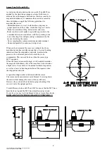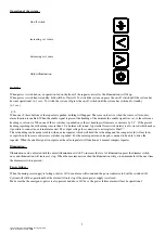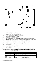
J4
: mains connector (no. 1through 4)
J5
: pilot/course alarm connector (no. 12 through 17)
J6
: NMEA output(2x) connector (no. 18 through 21)
J12
: External dimmer connector (PWM) (no. 22 through 25)
F1
: fuse 1A internal power /- 12Vdc
F2
: fuse 1A internal power 5Vdc
P1
: Uout coursesetter / maximum outputvoltage / *manufacturer setting / 6Vdc/300˚= 20mV/˚
P2
: Uref coursesetter / reference outputfor coursesetter function / *manufacturer setting / 1.25Vdc
P3
: Uref synchro / amplitude for rotor synchro / *manufacturer setting / 8Vtt
P4
: Current limeter of the power supply / *manufacturer setting /
P5
: Voltage output of the power supply / *manufacturer setting / +12Vdc +tol 0.4
P6
: Balance of the power supply / *manufacturer setting / +12Vdc=-12Vdc
D29
: +12Vdc indication
D30
: -12Vdc indication
D10
: processor program running indication
D11
: processor reset indication
J8
: selection jumper
* manufacturer setting -
Do not change these settings. If settings are changed the system will
not function properly.
21
xfiles\\tek\in11\doc\handleiding_in11b_eng.lwpp
status: definite date: 30-9-2002
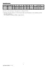
position
jumper on
jumper off
remarks
JMP1
auto power on
autopower off
power supply present system switches on
JMP3
course setter on
course setter off
compass card indicater reference heading
JMP5
JMP7
HCHDM
HEHDT
choice output string

