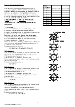
Compass adjustment of deviations :
In the electronic unit are 6 potentiometers and 3 switches for
compensation of the "A", "B", "C", "D", "E" and "V" deviations.
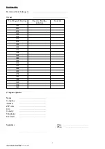
In order to determine the deviations of the repeater in respect to
the true magnetic heading a steering table must be made :
Steer the ship one full circle and check the differences (deviations)
between the true magnetic heading and the repeater indication on the
headings
N
,
NE
,
E
,
SE
,
S
,
SW
,
W
and
NW
.
A higher indication of the repeater means a -deviation.
A lower indication means a + deviation.
An explanation how to calculate the different adjustments
follows below.
"A" Adjustment :
A more or less equal deviation + or - on all headings, can be
neutralized by rotating the sensor in the bracket and a fine
adjustment can be done with the "A" potentiometer. On delivery this
potentiometer is set in the neutral position.
Do not rotate the sensor after adjusting the other deviation
components
. This will 'damage' the made adjustments. Therefore
adjust A-deviation before starting the adjustments of the other
deviation components (B, C, D and E).
If the A-deviation is more than 5 deg., rotate the sensor in the bracket
first, but not further than the scale on the sensor. Then use the "A"
potentiometer for fine adjustment.
Formula to calculate A correction is :
A=(dN+dNE+dE+dSE+dS+dSW+dW+dNW)
/
8
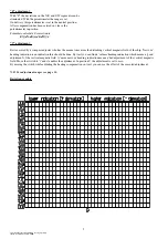
"B" adjustment :
With "B" the deviations on the E/W segment can be eliminated. With
the switch the compensation direction can be selected: +, 0 or -.
With the potentiometer the range is set.
With the switch in "0" position no correction is made.
After compensation has been carried out, leave the potentiometer and
the switch in set position.
Formula to calculate B correction is :
B=(dE-dW)/2
"C" adjustment:
With "C" the deviations on the N/S segment can be eliminated. With
the switch the compensation direction can be selected : + or -.
With the potentiometer the range is set.
With the switch in "0" position no correction is made.
After this has been carried out, leave the potentiometer and the
switch in position.
Formula to calculate C correction is :
C=(dN-dS)/2
"D" adjustment :
With "D" the deviations on the NE/SE and SW/NW segments can be
eliminated. With the potentiometer the range is set.
On delivery this potentiometer is set in the neutral position.
After compensation has been carried out, leave the potentiometer in
position.
Formula to calculate D correction is :
D={(dNE-dSE)+(dSW-dNW)}/4
10
xfiles\\tek\in11\doc\handleiding_in11b_eng.lwpp
status: definite date: 30-9-2002
TRUE
MAGNETIC
HEADING
INDICATION
DEVIATION
000
045
090
135
180
225
270
315


