background image

Trouble shooting :

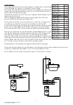
It may happen that the repeater does not function properly. It sometimes seems to show the right 
course and sometimes not, only give 1 or 2 headings or rotates constantly.
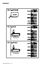
First of all the sensor cable must be checked. For this you need a multimeter in resistance mode. 
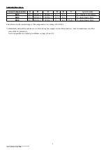
Disconnect the sensor cable from the electronic unit. You can check the disconnected cable as 
shown in tables on the right side of this page.
All the measured resistances may be 10% more or less. Important is that the multimeter does not 
indicate an open or short circuit.
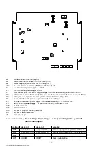
Check the internal powersupply when the repeater rotates constantly. D29 en D30 on the 
processor PCB must lit up to indicate power supply is OK.

You must make sure that there is no short circuit between any of the leads. A damaged coil is 
very unlikely in case of the MC4 sensor, but can occur with the sensors MC2 an MC5. 
So, first carefully check the cable, watertight connector and other junctions  (if they are present). 
In most cases an eventual problem may be found here. If they prove to be in order, then the 
defect is inside the sensor. In this case the sensor must be repaired by an authorised engineer.

If the Type 11-B repeater does not respond at all and the instrument illumination does not work 
either, the cable from repeater to electronic unit must be checked, as well as the mains and the 
fuses. Make sure the voltage level is between 18 to 35 volts and that the power supplies 
connections in the electronic unit are not reversed. If the power supplies are reversed the system 
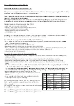
will not operate. The system is protected for incorrect connection of the power supplies. Connect 
the power supplies in the correct way. If you need to replace the fuses use glass slow blow fuse  
1A ( 20 x 5 mm). Location of the fuses is to the left above the mains connector.

The right  polarity for connecting the power supplies are indicated in the wiring diagram. 

Wrong or bad connections allmost never can inflict damage to the instrument(s). Only the mains could damage the electronic unit 
if connected to terminals other then terminal 1/3 (+18 to 35 Vdc) and terminal 2/4 (0 Vdc).

In case a problem can not be located or solved, please contact your local dealer or I.T. Holland.

13

xfiles\\tek\in11\doc\handleiding_in11b_eng.lwpp
status: definite date: 30-9-2002

Sensor MC4

Ohm

White- Black

90

Yellow- Blue

140

Yellow - Red

140

Blue - Red

140

Screen - Brown

-

Sensor MC2

Ohm

White- Black

-

Yellow- Blue

140

Yellow - Red

140

Blue - Red

140

Red - Brown

90

Sensor MC5

Ohm

White- Black

680

Yellow- Blue

140

Yellow - Red

140

Blue - Red

140

Red - Brown

90

Summary of Contents for IN11-B

Page 1: ...Manual Electronic Compass System TYPE11 B...

Page 2: ...Deviation graphic 11 Deviation table 12 Trouble shooting 13 Wiring diagram 14 Operation of the compass system 15 Compensation ranges 16 Declaration of conformity 17 Latest compensation adjustment posi...

Page 3: ...1 indication 2 aanwijzing 2 diff 2 verschil 2 remark s opmerking en 000 045 090 135 180 225 270 315 000 Tested by getest door authograph handtekening Local geomagnetic data 2 6 2003 Inclination deg 6...

Page 4: ...efered to read a magnetic compass directly When the sensor type MC5 is applied it is a stand alone compass system for see going vessels in a restricted area within 30 miles Outside this area it is per...

Page 5: ...THE CENTER OF THE BRACKET AND THE CENTER OF THE MAGNETIC COMPASS MAY NOT DIFFER MORE THAN 1 mm LARGER ERRORS THAN 1 mm WILL RESULT IN A NOT FULLY ADJUSTABLE COMPASS SYSTEM Centering the sensor place...

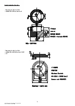
Page 6: ...ting brackets Mounting bracket for MC4 combination with anschutz coil Mounting bracket for MC4 combination with Robertson CD109 coil 6 xfiles tek in11 doc handleiding_in11b_eng lwpp status definite da...

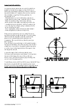
Page 7: ...lines and the repeater has a nervous heading indication when the ship pitches and rolls it indicates the presence of a vertical magnetic field which has to be compensated This can only be done when th...

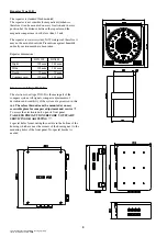
Page 8: ...main part of the compass system All signals compass adjustments of deviations and sensitivity of the system are processed in this unit Therefore this unit must be mounted at an easy accessable place...

Page 9: ...on solvable accuracy problems of the system cable extensions up to 100m are possible Connecting the compass cable in the electronic unit IN11 B remove the black outer insulation over a length of appr...

Page 10: ...than the scale on the sensor Then use the A potentiometer for fine adjustment Formula to calculate A correction is A dN dNE dE dSE dS dSW dW dNW 8 B adjustment With B the deviations on the E W segmen...

Page 11: ...of the ship Nervous heading indication is an indication this should be done By trail you can find a calmer heading indication which means a good adjustment of the vertical magnetic field A more nervo...

Page 12: ...de City Country Telephone Facsimile Signature Date Place 12 xfiles tek in11 doc handleiding_in11b_eng lwpp status definite date 30 9 2002 True Magnetic Heading Repeater Heading indication Deviation 00...

Page 13: ...repeater does not respond at all and the instrument illumination does not work either the cable from repeater to electronic unit must be checked as well as the mains and the fuses Make sure the volta...

Page 14: ...Wiring diagrams 14 xfiles tek in11 doc handleiding_in11b_eng lwpp status definite date 30 9 2002...

Page 15: ...ble to connect an external alarm unit The output voltage for connection to a riverpilot is 20mV The set heading can be made visable with an extra repeater which will hold the set heading and the compa...

Page 16: ...ery Local circumstances can effect some of the set parameters for switch positions and adjust possibillities see pages 20 and 21 16 xfiles tek in11 doc handleiding_in11b_eng lwpp status definite date...

Page 17: ...dress see above Country The Netherlands Standards used SOLAS 74 as amended Regulation V 12 r b IMO Resolutions A 694 17 A 813 19 IEC 60945 IEC 61162 1 ISO11606 2000E ISO11606 2001E Test report no 9501...

Page 18: ...t compensation adjustment positions Date Date Compass adjuster Compass adjuster Date Date Compass adjuster Compass adjuster 18 xfiles tek in11 doc handleiding_in11b_eng lwpp status definite date 30 9...

Page 19: ...Date Date Compass adjuster Compass adjuster Date Date Compass adjuster Compass adjuster 19 xfiles tek in11 doc handleiding_in11b_eng lwpp status definite date 30 9 2002...

Page 20: ...to the cosine circuit MC4 P12 manufacturer setting balance adjuster of the A adjuster P13 manufacturer setting adjustment maximum range B adjuster P14 manufacturer setting balance adjuster of the V a...

Page 21: ...supply manufacturer setting P5 Voltage output of the power supply manufacturer setting 12Vdc tol 0 4 P6 Balance of the power supply manufacturer setting 12Vdc 12Vdc D29 12Vdc indication D30 12Vdc indi...

Reviews: