background image

IQ32 SDR TRANSCEIVER OPERATIONS MANUAL 


P a g e

 | 36 

Frequency Tuning 
 

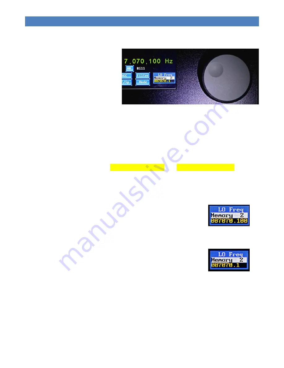
The 

LO Freq 

widget displays the cur-

rent  frequency  of  operation  and  the 
last selected memory. Memory selec-
tion will be discussed in the next sec-
tion. 
 
The current  frequency is adjusted by 
rotating  the  right  rotary  encoder 
clockwise  to  increase  and  counter-
clockwise to decrease the frequency. 
 
The frequency is displayed on the bottom line of the widget. In SSB and CW modes, the fre-
quency is displayed in large green characters as shown in Figure 47.  
 
You can adjust the step size or tuning step resolution of the frequency by pressing and holding 
in  the  right  rotary  encoder  and  rotating  clockwise  for  smaller  steps  or  counterclockwise  for 
larger steps.  
 
If a PS2 keyboard is attached, the 

LEFT ARROW

 (

)

 and 

RIGHT ARROW

 (

)

 keys may 

be used to adjust the tuning step resolution of the frequency. 
 
A  third  method  is  available.  With  a  small  pointed  stylus  touch  the  left  edge  of  the  frequency 
display to increase the tuning step size. Touch the right edge to decrease the tuning step size. 
 
Figure  48  shows  the  minimum  tuning  step  of  1  Hz,  with  all  digits  in 
yellow.  
 
Figure 49 shows a tuning step size of 100 Hz indicated by the yellow 
digits. The 1 and 10 digits are grayed out to indicate they are not ac-
tive. 
 
This tuning step adjustment  allows  steps sizes  from 1 Hz to 100MHz. 
In  normal  operation,  this  is  limited  to  35MHz.  When  setting  the  fre-
quency  offset  for  use  with  a  transverter,  the  full  adjustment  range  is 
possible. This will be covered in the next section. 


Figure 48: Minimum 

Tuning Step of 1 Hz 


Figure 47: Frequency Tuning 


Figure 49: Tuning 

Step of 100 Hz 


Summary of Contents for IQ32

Page 1: ...IQ32 SDR Transceiver Operations Manual Software Version 1 200 Manual Revision February 19 2020 ...

Page 2: ...ired Accessories 8 Optional Accessories 8 Setup 8 Startup 8 Configuration 8 Firmware Upgrade 9 Public Source Files 9 Operation 10 Non Volatile Memory 11 Home Screen 12 Mode Selection 13 Settings Screens 16 Main Settings 17 Advanced Settings 18 Function Editing with a Keyboard 20 Keyboard Fn Setting 21 Screen Fn Settings 29 Tags Settings 32 Frequency Tuning 36 Frequencies Screen 37 Receive Filter S...

Page 3: ...eter Calibration 59 Appendix Tags Macros Buttons and Keyboard 60 Tags 60 Macros 61 Default On Screen Button Functions 62 SSB HOME SCREEN Buttons 62 CW HOME SCREEN Buttons 62 PSK HOME SCREEN Buttons 62 Keyboard Function Keys 63 Block Diagrams 64 Keyboard Cheat Sheet 65 F1 Call CQ 65 F2 Send Your Name and QTH 65 F3 Send your Rig information 65 F4 Send your Antenna information 65 F5 Confirm Called St...

Page 4: ...o CW mode 65 F10 Toggles Transmitter Between Receive and Transmit Mode 65 F11 Clear Transmit Buffer 65 F12 Step through Memory Buttons Memory 1 to Memory 5 65 LEFT ARROW and RIGHT ARROW Increase or decrease tuning resolution 65 UP ARROW and DOWN ARROW Step through Memory 1 to Memory 14 65 ...

Page 5: ... Advanced Screen 18 Figure 20 Move Cursor with Arrow Key 20 Figure 21 Use TAB to Select the Label 20 Figure 22 Keyboard Fn Screen 21 Figure 23 Function Key F1 22 Figure 24 Function Key F2 23 Figure 25 Function Key F3 23 Figure 26 Function Key F4 24 Figure 27 Function Key F5 24 Figure 28 Function Key F6 25 Figure 29 Function Key F7 25 Figure 30 Function Key F8 26 Figure 31 Function Key F9 26 Figure...

Page 6: ...een 45 Figure 61 CW Split Operation Transmit Frequency Screen 45 Figure 62 CW Split Operation Screen 46 Figure 63 Station Call Sign and Name 47 Figure 64 FFT Spectrum View 48 Figure 65 Waterfall View 48 Figure 66 SSB Home Screen 49 Figure 67 PSK Home Screen 51 Figure 68 VFO Tuned to 7070kHz 51 Figure 69 Decoded Signal at 14 073 548Hz 52 Figure 70 VFO Set At 14071kHz 52 Figure 71 Starting a QSO Wit...

Page 7: ...e in Bold no small caps Advanced Widget Names All widget names have the first letter capitalized and the complete name in Bold Mode Tags All tags are bold and blue StnCS 51 51 255 Macros All macros are bold and violet USB 153 0 255 Fn Keys Keyboard Fn keys are bold and highlight yellow F3 Widget and Icon refer to the same on screen feature HOME SCREEN and OPERATION SCREEN refer to the same screen ...

Page 8: ...ilt in keyer for CW operation and a PSK encoder and decoder for PSK operation The IQ32 does not require an external computer to take advantage of all the features The operating firmware of the IQ32 is easily upgraded by downloading the latest firmware to a memory stick The memory stick is connected to the USB port on the radio and the radio han dles the upgrade Connect a suitable antenna or dummy ...

Page 9: ... Spurious and Harmonics 50dBc typical o Built In Keyer 5 to 35 WPM Iambic Mode A B Adjustable dot dash weighting Straight key mode DC Power 13 8VDC 2A max o 10VDC minimum o 15VDC maximum Antenna Connector BNC Antenna Port The IQ32 can tolerate short duration antenna faults ranging from short to open circuit Good operating practice dictates that a match of 3 1 or better is required for efficient lo...

Page 10: ...1 RX I Q Output 3 5mm TRS a Tip I b Ring Q c Sleeve Ground 2 Headphone Output 3 5mm TRS a Tip Left b Ring Right c Sleeve Ground 3 Speaker Mic 3 5mm TRRS a Tip SPKR b Ring 1 MIC c Ring 2 PTT d Sleeve Ground 4 CW Key 3 5mm TRS a Tip Dit Straight Key b Ring Dot c Sleeve Ground Figure 1 Left Side Panel ...

Page 11: ...e 4 Right Side Panel 1 Power Switch 2 Power Amp connection 3 5mm TRS a Tip Band Data b Ring PTT c Sleeve Ground 3 Power Connector 5mm X 2 1mm center positive 4 PS2 Keyboard Connector 5 USB Type A 6 Antenna connection BNC Figure 2 Right Side Panel ...

Page 12: ...ht Rotary Encoder Frequency Control Frequency Adjustment rotate Press rotate and release o Change the frequency step size 1 10 100 etc Hz The right rotary encoder on the front panel selects the desired operating frequency for trans mit and receive It is also used to calibrate the touch screen and to initiate a firmware upgrade Left Rotary Encoder Rotate adjust AF gain 0 to 100 Other parameters are...

Page 13: ...PSK o Contact Call Sign NM CW PSK o Contact Name Tune PSK o Tune v PSK Settings o AF Gain 0 to 100 70 o RF Gain 0 to 100 100 o AGC Mode 0 CW 1 Digi 2 SSB 3 Off o Mic Gain 0 to 80 30 o TX Level 6 to 22 22 o Side Tone 6 to 29 20 o CW Speed 5 to 35 WPM 12 o CW Weight 7 to 15 10 o Advanced Key Mode 0 Straight 1 Iambic A 2 Iambic B 3 Weight Dah 4 Weight Dit Dah Mic Bias 0 Bias Off 1 Bias On AGC Thrsh 5...

Page 14: ...ry 3 14 060 000 Hz CW o Memory 4 21 060 000 Hz CW o Memory 5 10 000 000 Hz USB o Memory 6 3 580 000 Hz PSK U o Memory 7 7 070 000 Hz PSK U o Memory 8 14 070 000 Hz PSK U o Memory 9 21 080 000 Hz PSK U o Memory 10 15 000 000 Hz USB o Memory 11 3 985 000 Hz LSB o Memory 12 7 285 000 Hz LSB o Memory 13 14 285 000 Hz USB o Memory 14 29 000 000 Hz USB o F Offset 000 000 000 o Edit o LO Freq AGC o CW fo...

Page 15: ... jack on the right side panel 6 If you have a straight key or paddle connect it to the Key jack on the left side panel 7 If you have a PS2 keyboard connect it to the PS2 keyboard connector on the right side panel Startup 1 Turn on the power supply 2 Turn on the power switch on the right side panel of the IQ32 3 A SPLASH SCREEN will be displayed followed by the HOME SCREEN 4 If the touch screen has...

Page 16: ... ve7pke IQ32 Files Download the most recent zip file and save it to a safe location on your computer Unzip this file Place the image bin file in the root of a USB flash drive having a capacity of 4GB or less With the IQ32 powered off insert the USB drive into the USB connector on the right side panel of the IQ32 Press and hold down the frequency encoder while powering on the IQ32 The screen will r...

Page 17: ...dates to the documentation After a few seconds you should see the screen pictured in Figure 5 It is the HOME SCREEN From here you can start your journey at each subsequent power up you will be returned to the HOME SCREEN after the SPLASH SCREEN is briefly displayed The software has multiple screens that are accessed by touching the appropriate place on the touchscreen These widgets are multifuncti...

Page 18: ...are preserved for future use When the power is turned off and later restored the value of the many parameters retrieved from memory are the same as previously defined Frequency of operation mode filter AGC split frequency Tx Level and frequency increment step size are saved in the last selected memory location Memory 1 Memory 14 These memory locations are discussed in a later section of this manua...

Page 19: ...o the right the AGC selection is CW AGC operation will be described in a later section of this manual Call and Name For CW and PSK operation the but tons shown at the right are displayed on the HOME SCREEN With a PS2 keyboard attached to the IQ32 you may enter the call sign and the name of your contact They will be transmitted as configured for the keyboard Fn keys This is discussed in a later sec...

Page 20: ... It will switch to the desired mode and the mode s HOME SCREEN If you selected the wrong mode you must hit the Mode button Figure 7 on the HOME SCREEN to return to the MODE SELECTION SCREEN Then select the desired mode Touch the LSB USB button Figure 9 to go to the LSB HOME SCREEN Figure 10 Once on the LSB HOME SCREEN or any HOME SCREEN you can either operate the radio access the MEMORY MANAGER LO...

Page 21: ...d in large green digits between the FFT window waterfall or spectrum display and the widgets buttons on the bottom third of the screen There are 7 buttons on the CW HOME SCREEN which are shortcuts to other functions to be de scribed in this manual On the MODE SELECTION SCREEN touch the PSK U PSK L button Figure 13 to go to the PSK HOME SCREEN Figure 14 Once on the PSK Home Screen you can either op...

Page 22: ...your transmitter to your antenna See Figure 16 In this mode the left rotary encoder has been set to adjust the TX Level Adjust the left rotary encoder to set the desired power output Touch the Tune button again to turn off the carrier When the IQ32 is connected to the HobbyPCB Hardrock 50 power am plifier you can set the power level of the HR50 and activate your antenna tuner The carrier is transm...

Page 23: ...buttons on the left side which go directly to settings whose values can be set with the left rotary encoder The four buttons on the right take you to sub screens of the SETTINGS SCREEN for functions that you will not need to change nearly as often With the eight most common settings the rotation of the left rotary encoder causes the value to change immedi ately and the numeric value of the option ...

Page 24: ...usts the power output of the radio Range is 6 to 22 See the Radio Setup section for more details Side Tone Side tone level adjusts the level of the side tone present in the headphones or speaker CW Speed This control adjusts the words per minute WPM rate of the built in keyer The range is 5 to 35 WPM CW Weight This modifies the defined dot to dash ratio 1 3 The range is 7 0 7 to 15 1 5 With a sett...

Page 25: ...ode of the internal keyer 0 Straight Key 1 Iambic_A 2 Iambic_B 3 Weight Dah 4 Weight Dit Dah The CW weight and speed are set on the SETTING SCREEN Mic Bias This is either On 1 or Off 0 If you are using an electret microphone you need this bias voltage for the microphone to function properly AGC Thrsh Adjusts the AGC Threshold i e the point where AGC starts to function Default value is 400 for norm...

Page 26: ...CREEN CALIBRATION SCREEN If the calibration is sufficiently far out of whack you won t be able to select this option by touching the screen In that case power down the IQ32 power it back up and promptly and simultaneously press both of the rotary encoders inwards This selects the same CALI BRATION SCREEN Factory Rst Use this button if you mess up settings so badly that the radio is not oper ationa...

Page 27: ...he following is a description of cursor movement LEFT ARROW and RIGHT ARROW keys move the cursor along a string of displayed characters Characters may be added or deleted at the cursor lo cation The TAB key switches between editing of the string and the key s label This applies to SCREEN FUNCTION SCREEN KEYBOARD FUNCTION SCREEN and TAGS SCREEN The UP ARROW and DOWN ARROW keys allow you to switch t...

Page 28: ...On the KEYBOARD FUNCTIONS SCREEN you can touch any of the on screen buttons grouped in the top left corner of the screen These correspond to the twelve F1 through F12 keyboard buttons and adjust the function that each performs By default the twelve function keys are dedicated to the following actions F1 1 Call Transmit your callsign CW PSK mode only F2 2 Name Transmit your name and location CW PSK...

Page 29: ... follows Tx turns on the transmitter CQ seek you is sent three times de from is sent followed by MyCall your Amateur Radio call sign which will be described in the sec tion on Tags pse the abbreviation for please is transmitted k the abbreviation for OK is also transmitted RX returns the IQ32 to receive mode Note there is room for two lines of text commands tags on the screen The cursor the char a...

Page 30: ...on F2 is used in CW and PSK31 modes to send your name and your location QTH to the station you are working See Figure 24 Keyboard function key F3 is used while in CW PSK31 mode to send information about your rig If you touch this button the screen shown in Figure 25 is displayed Figure 24 Function Key F2 Figure 25 Function Key F3 ...

Page 31: ...creen button you will see a screen similar to Fig ure 26 Keyboard function key F5 is used near the end of a CW or PSK31 QSO The label on the screen for function key F5 is BTU which is short for Back to You You can see this by selecting the fifth button on the KEY BOARD FUNCTIONS SCREEN A screen similar to Figure 27 is displayed Figure 26 Function Key F4 Figure 27 Function Key F5 ...

Page 32: ...n cus tomize this by touching the sixth on screen button A screen like Figure 28 will be shown The response to keyboard function key F7 is programmed by default to change the IQ32 to USB Upper Side Band mode as can be seen in Fig ure 29 Note that this is accom plished by issuing the USB macro Figure 28 Function Key F6 Figure 29 Function Key F7 ...

Page 33: ...uing a macro named CW If you are attempting to make a con tact on SSB and the other station is simply not hearing you well enough to make out your callsign for exam ple you might want to quickly switch to CW mode and send your infor mation knowing that CW signals are often discernible under conditions where SSB signals are inadequate and hoping that the other station understands Morse Code Instead...

Page 34: ... next subsequent press of the F10 key will switch from Transmit back to Receive Selecting button 10 on the KEYBOARD FUNCTIONS SCREEN will look similar to Figure 32 Keyboard Function Key F11 is used in PSK31 mode to empty out the transmit buffer in preparation for the user to type in a new string of text to be sent Touching button 11 on the KEYBOARD FUNCTIONS SCREEN looks like Figure 33 Figure 32 F...

Page 35: ...cycle through the first five memory locations in the Memory Manager Memory 1 through Memory 5 This provides a means to easily move be tween 5 of your favorite operating frequencies and mode NOTE In all cases pressing the TAB key will enable editing of the label Figure 34 Function Key F12 ...

Page 36: ...ed on the SCREEN FUNCTIONS SCREEN If the factory default operation of these buttons does not suit your method of operation you may edit the label on the button as well as the function that it performs You change the function invoked by one of these buttons by programming in one or more macros on this screen We have already seen a couple of the macro tags earlier when we were discussing the program...

Page 37: ... 3 You may quickly step through these 4 modes on the SSB HOME SCREEN by touching the on screen AGC button Note that the on screen AGC button is programmed by invoking a macro called NxAGC which means next AGC mode Refer to the Appendix for a list of all the available macros Figure 37 shows the default pro gramming of the WF Sp button With the default setting touching this button on the SSB HOME SC...

Page 38: ... CW PSK U PSK L USB The audio filter is set to No Filter in case the current audio filter is too narrow for proper operation of the next mode NOTE CWR is not included in this sequence You may program four similar buttons located on the CW HOME SCREEN us ing the methods described above In CW modes the on screen Filter button works like the same named button in SSB modes The difference being that th...

Page 39: ...y touch the on screen but ton for the Tag that you want to edit The first 5 buttons are self explanatory MyName your name normally just your first name MyCall your Amateur Radio callsign QTH your home or operating loca tion You may want to put City State or your Maidenhead Grid Square or both if there is room Rig your radio hardware for ex ample IQ32 Ant your antenna T6 through T10 tags are availa...

Page 40: ... e 33 Figure 41 shows the factory default setting for the MyName button John Doe You should change this to your own name Figure 42 shows the default text in the MyCall tag Enter your call sign in this tag Figure 41 MyName Tag Figure 42 MyCall Tag ...

Page 41: ...d to reflect either your home city state province Maiden head Grid Square or some other indication of the location from which you are operating Figure 44 is currently configured for the IQ32 in the default setting This may be changed if you desire Figure 43 QTH location Tag Figure 44 Rig radio type Tag ...

Page 42: ...shown in Figure 45 This field may be edited for your antenna type Tags T6 through T10 are currently unused and available for your use They are blank as shown in Figure 46 NOTE In all cases pressing the TAB key will enable editing of the label Figure 45 Ant antenna type Tag Figure 46 T6 Tag ...

Page 43: ...r larger steps If a PS2 keyboard is attached the LEFT ARROW and RIGHT ARROW keys may be used to adjust the tuning step resolution of the frequency A third method is available With a small pointed stylus touch the left edge of the frequency display to increase the tuning step size Touch the right edge to decrease the tuning step size Figure 48 shows the minimum tuning step of 1 Hz with all digits i...

Page 44: ...cond memory button and configure it as desired Returning to the first memory but ton the previously saved parameters are restored After selection of a memory button any operating changes made such as a new frequency are saved to the memory button s non volatile memory You do not have to manually save the information NOTE This means you may inadvertently change the configuration of a memory button ...

Page 45: ...will appear on the desired button The next button label will appear to be edited To end the editing session and save the new button name touch the LO Freq widget Button names may contain up to 10 characters including space and punctuation The F Offset button is used for adding an offset to the displayed frequency of the IQ32 when using a transverter For example if you have a trans verter with an I...

Page 46: ...to your operating frequency Next adjust your operating frequen cy using the right rotary encoder for 28MHz The displayed operating frequency will be 144MHz Figure 54 Note In PSK mode the large green frequency display is not available It is your responsibility to track the relationship of the F Offset and the IQ32 operating frequency to the actual operat ing frequency of the transverter Figure 53 S...

Page 47: ...arrower filter until the narrowest one is reached at which time you wrap around to the widest one all over again The six filter bandwidths are as follows F0 4 000 Hz 0 4000 F1 3 300 Hz 300 3000 F2 2 400 Hz 300 2700 F3 1 000 Hz 300 1300 F4 300 Hz 400 700 F5 100 Hz 500 600 As you may recall we previously mentioned that there are on screen buttons on the SSB and CW HOME SCREENS that allow you to sele...

Page 48: ...CW Weight function the length of a dah may be varied from the proper 1 3 relationship The adjustment range is 7 0 7 x the duration to 15 1 5 x the duration For example at 10 words per minute a dit is 120ms duration and a dah is 360ms A setting of 10 1 0 maintains this proper re lationship If the weight is set to 8 0 8 the dah duration is changed to 288ms Similarly if the weight is changed to 12 1 ...

Page 49: ...Time is a function of the CW Speed setting even if you are using a straight key The lower limit of the hang time is 15WPM The Hang Time is 2 word gap times or 10 dit times at the CW Speed setting For example at 15WPM 1 dit time is 80ms The Hang Time is 10 x 80ms 0 80 seconds To control the hang time simply adjust the CW Speed This works great with a straight key If you are using a paddle your hang...

Page 50: ...displayed You may calibrate the touch screen anytime you are having trouble initi ating an action when touching the screen The calibration option is always available at turn on It may also be initiated from the ADVANCED SCREEN by touching the Cal Screen button Figure 58 shows the CALIBRATION SCREEN Follow the prompts on the screen to complete the touch screen calibration NOTE If you accidently acc...

Page 51: ...ion of this manual there are 4 programmable control buttons on the screen marked AGC Filter WF Sp and Mode The AGC button selects the Automatic Gain Control mode The Filter button selects the audio filter bandwidth as does pressing and releasing the left rotary encoder The WF Sp button toggles the FFT display area of the screen between Waterfall view Figure 64 and Spectrum view Figure 65 The Mode ...

Page 52: ...ng but they listen on a different announced frequency such as 1kHz higher in the band On the CW HOME SCREEN Figure 59 touch the on screen Split button The display will change similar to Figure 60 Next set your desired transmit fre quency Figure 61 In this example we tuned to 7 031MHz or 1kHz higher than the receive frequency Once you have set the transmit fre quency touch the button which was re l...

Page 53: ...digits This screen shows the operation of CW in split frequency mode The Tx frequency 7 031MHz in this example and the Rx frequency 7 030MHz in this example are both displayed The SetTx button has been renamed Join If you no longer wish to operate in split mode touch the Join button Split frequency operation will be dis abled and you will be returned to a screen similar to Figure 59 Figure 62 CW S...

Page 54: ...TION SCREEN you will transmit the previously configured strings such as Tx CQ CQ CQ de myCall pse k k k Rx The characters you have typed or initiated from a function key are displayed directly above the TX frequency The characters scroll to the left as they are sent The keyboard is also used to enter the calling station s call sign and the operator s name as shown in Figure 63 These are associated...

Page 55: ...dicates the tuned frequency This Spectrum display allows you to see other signals in your 4kHz chunk of the radio spec trum A taller blue bar means a stronger signal The Waterfall view Figure 65 is a more complex way to view signals Both time and intensity are shown on the screen The signal strength is shown in color ranging from black no signal to red a very strong signal The color display slides...

Page 56: ...election of the Automatic Gain Control Repeated touches of this button cycle through the various AGC modes The WF Sp button enables selection of the Spectrum or Waterfall FFT display The Filter button allows selection of the audio bandpass filter as previously discussed The Mode button allows you to quickly change to a different operational mode CW LSB USB PSK L PSK U In the upper right corner of ...

Page 57: ...o the microphone You may also initiate transmission by pressing the F10 function key on an attached keyboard and then speak into the microphone You will see your transmitted audio spectrum on the FFT display during transmit Pressing the keyboard F10 key or releasing the PTT switch after speaking returns the radio to the receive state You will also notice on the display that there is an S meter bot...

Page 58: ...ight corner 7070kHz and the tuning step is 1kHz because the 3 least significant digits of the frequency display are grayed out Memory preset Memory 7 has been selected The function of the 2 buttons CS and NM are described in the section Keyboard Operation in CW The keyboard and these 2 buttons function the same in PSK and CW In Figure 68 the VFO is set at 7070kHz and the signal being decod ed is a...

Page 59: ... waterfall display at the location of the desired signal or frequency The AF frequency will be updated appropri ately Touch the Tune button so the label changes from Tune to Tune v Turn the right rotary encoder to ad just the VFO to 7069kHz as shown in Figure 70 Tune indicates that the right rotary encoder will adjust the frequency of the AF display Tune v indicates that the right rotary encoder w...

Page 60: ...the Mode widget indicates TX In this example F1 turned on the transmitter sent the CQ string of characters and then turned off the transmitter The other keyboard function keys operate in a similar manner As defined not all Fn keys will turn on and off the transmitter This may be configured on the KEYBOARD FUNCTION SCREEN Figure 72 shows a QSO with A2BCD Bill In this example the transmitter must be...

Page 61: ...ursor through 2 pixels above the cursor However the DAC s AGC is con trolled by the peak magnitude as described above for Mode 0 SSB AGC In the SSB mode the PGA s AGC is controlled by summing the magnitude bins over the entire audio spectrum from 300 3500 Hz The DAC s AGC is controlled by the peak magnitude as described above Off In the Off mode the PGA s AGC is controlled by the RX_RF value which...

Page 62: ...ollowing three modes it is then set correctly for the other two modes SSB On the ADVANCED SCREEN adjust the Mic Bias for proper operation of the type of microphone that you are using Set to 1 to provide a mic bias voltage for the RS UV3 needed for an elec tret microphone element or to 0 for no bias non electret microphones If your microphone requires a bias voltage and you have this option set to ...

Page 63: ...put to 5 Watts first select the Tx Level from the SETTINGS SCREEN On the MODE SCREEN touch the Tune button This will turn on the transmit carrier Adjust the Tx Level shown on the Mode widget for 5 Watts power output as shown on your wattmeter or other power monitoring device Touch the Tune button on the MODE SCREEN one more time to turn off the transmitter Do not increase the Tx Level past the pos...

Page 64: ...ignal generator We will use WWV for this procedure 1 Select PSK U 2 Tune to WWV at 10MHz or 15MHz Figure 77 3 Touch the Tune button so it indi cates Tune v 4 Adjust the frequency in the LO Freq widget to 1kHz less than the desired signal 9 999MHz or 14 999MHz 5 Touch the Tune button so it indi cates Tune 6 Touch Setting the widget then the AGC Mode button Set the AGC to 3 Off 7 Touch the Setting w...

Page 65: ...uency to 1000Hz This may be 999Hz 12 Adjust Freq Cal to make the WWV signal coincide with the red frequency marker Note The blue signal WWV will disappear behind the red marker 13 Your operating frequency is now calibrated Figure 80 14 Return the Setting widget to AF Gain 15 Be sure to return AGC RF Gain WF Sp and LO Freq to your desired operating condi tions This procedure can be done with any ca...

Page 66: ...dBm To calibrate the S meter select a fre quency in the amateur radio band Set the mode to CW and add a nar row filter At the selected frequency apply a 73dBm signal to the antenna input of the IQ32 On the ADVANCED SCREEN touch the RSL Cal button Then touch the Set ting widget to return to the CW HOME SCREEN Figure 81 Center the received signal on the red line of the FFT Spectrum display Using the...

Page 67: ... executed when the on screen button is touched These 10 on screen buttons are only programmed using one or more macros A standard keyboard has 12 programmable function keys labeled F1 through F12 You can pro gram the action s performed by each of those function keys These function keys can be assigned combinations of literal text strings tag names and or Macros When a function key is pressed any l...

Page 68: ...hers F0 F1 F2 F3 F4 NxFil5 Toggles among Audio Filter 0 and 5 others F0 F1 F2 F3 F4 F5 Rx Change to Receive Mode Tx Change to Transmit Mode Tx Rx Toggle Change to Rx if in Tx mode Change to Tx if in Rx mode Spect Change to FFT Spectrum view Wfall Change to FFT WaterFall view WF Sp Change to Waterfall if in Spectrum or to Spectrum if in Waterfall USB Change to Upper SideBand Mode LSB Change to Lowe...

Page 69: ...reen Button Functions SSB HOME SCREEN Buttons 1 NxAGC 2 WF Sp 3 NxFilt2 4 NxMode NoFilt CW HOME SCREEN Buttons 1 NxAGC 2 WF Sp 3 NxFilt5 4 NxMode NoFilt 5 CS edit StnCS 6 NM edit StnNM PSK HOME SCREEN Buttons 1 WF Sp 2 NxMode NoFilt 3 CS edit StnCS 4 NM edit StnNM ...

Page 70: ... change between 5 of your favorite operating frequencies These function keys are programmed with combinations of literal strings to be transmitted dur ing a CW or PSK QSO tags whose corresponding string values are to be transmitted during a CW or PSK QSO and functions which are executed Here are the default associations any or all of which can be easily changed by the user via the Keyboard Functio...

Page 71: ...IQ32 SDR TRANSCEIVER OPERATIONS MANUAL P a g e 64 Block Diagrams Figure 82 RF Section Block Diagram Figure 83 Digital Section Block Diagram ...

Page 72: ...and Callsign and send Back to You BTU F6 Send Thank You and Best Wishes 73 s F7 Change to USB mode F8 Change to LSB mode F9 Change to CW mode F10 Toggles Transmitter Between Receive and Transmit Mode F11 Clear Transmit Buffer F12 Step through Memory Buttons Memory 1 to Memory 5 LEFT ARROW and RIGHT ARROW Increase or decrease tuning resolution UP ARROW and DOWN ARROW Step through Memory 1 to Memory...

Reviews: