


Appendix D: Modbus-TCP Client Configuration Manager
45 (70)
Transaction Settings (continued)
Setting
Description
The minimum scan time will increase by adding more transactions.
Value range: 10 - 10000 (ms).
Unit ID
Only applicable for Modbus RTU servers. If the Modbus-TCP server work as a router to Modbus RTU
servers, it is possible to send transactions to a single Modbus RTU server using the unit ID.
Value range: 0 - 247; 255.
If not communicating with a Modbus RTU server, use the value 255 (default).
Starting
register
The starting Modbus server register or bit to write to/read from. Value range: 1 - 65536.
Elements
The number of elements to write/read.
When
EtherNet/IP
(Network 1) is
not exchanging
I/O data
Note: Only available for I/O mapped write transactions.
Clear data to Modbus server: only zeros will be transmitted.
Freeze data to Modbus server: the data that was stored last will be repeated.
Write safe value: choose a specific value to transmit for every element (See safe element value below).
Stop: no data will be transmitted to the Modbus server.
Data type
Write/read data either as two byte integers (uint16) or four byte integers (uint32).
Registers
The resulting amount of registers to write/read.
The calculation is based on the number of elements to read/write and the chosen data type.
Safe Element
Value
Note: Only available for write transactions.
A numeric value to send for every element if network 1 (EtherNet/IP) is not exchanging I/O data.
Startup-mode
Wait for data: all data for the transaction must have been sent from the EtherNet/IP network and
received by the linking device before the transaction is carried out.
Directly: the data is sent as soon as possible after start-up.
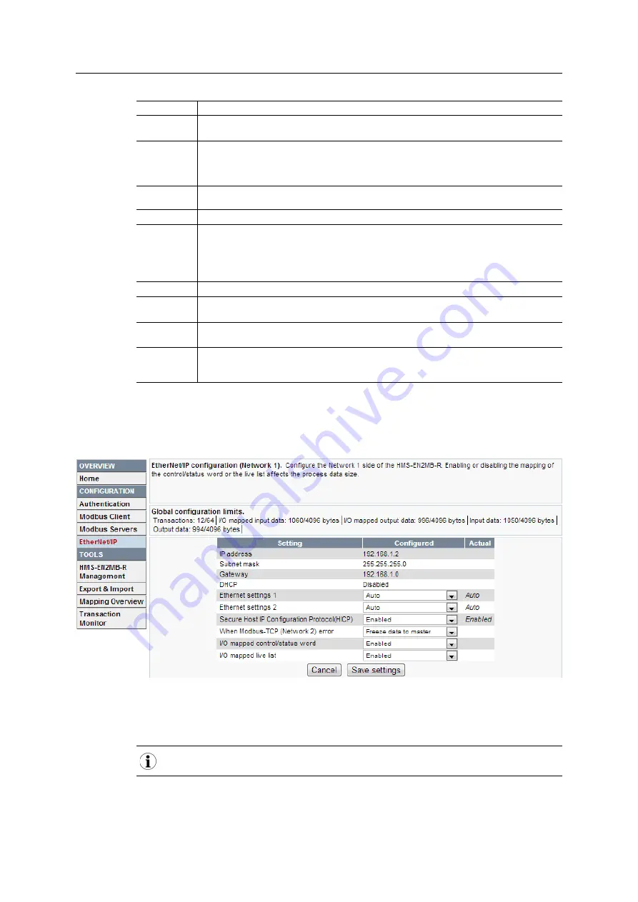
D.2.4
EtherNet/IP (Adapter Interface)
Select
EtherNet/IP
in the left-hand menu to configure the EtherNet/IP adapter interface of the
linking device.
The currently used settings are shown in the
Actual
column.
It is possible to override the TCP/IP and Ethernet settings set from the network by entering new
values in the
Configured
column and clicking
Save settings
.
The configuration must be applied for any changes to take effect.
Linking Device User Manual
scm-1202–181 2.0 en-US
Summary of Contents for Anybus HMS-EN2MB-R
Page 1: ...Linking Device EtherNet IP to Modbus TCP USER MANUAL scm 1202 181 2 0 en US ENGLISH...
Page 5: ...Linking Device User Manual scm 1202 181 2 0 en US H Copyright Notices 67...
Page 6: ...This page intentionally left blank...
Page 34: ...This page intentionally left blank...