


Intesis
TM
Modbus Server
– DALI
User Manual r1.3 EN
© HMS Industrial Networks S.L.U - All rights reserved
This information is subject to change without notice
URL
http
s
://www.intesis.com
38 / 39
2. Use the Auto Addr. Button to automatically assign a correlative address to each ballast.
Address of each ballast can be deleted at any time, using button Delete Addr. Multiple selection is possible (using
Shift and Control keys together with mouse-clicks).
Figure
A.10
Shot address association
Once each ballast has a short address, ‘Wink’ functionality in “DALI Network’ window is available for each ballast.
Wink functionality sets the ballast at maximum and minum level during a certain timeout, allowing to identify the
physical location of the ballast in the installation. After identifying it in the installation, change in short address might
be desired. It can be done again by using button ‘Chg Addr.’.
After address association, ballasts can be added in config. There is two ways for doing that:
-
Button ‘<<’: Selected ballast or ballasts in ‘DALI Network’ window will be added as a new ballast in
‘Configured ECG’ window. It allows multiple selection of ballasts from DALI Network window (using ‘shift’
or ‘control’ keys).
-
Button ‘<-‘: Selected ballast in ‘DALI Network’ window will be associated to existing/configured ballast in
‘Configured ECG’ window.
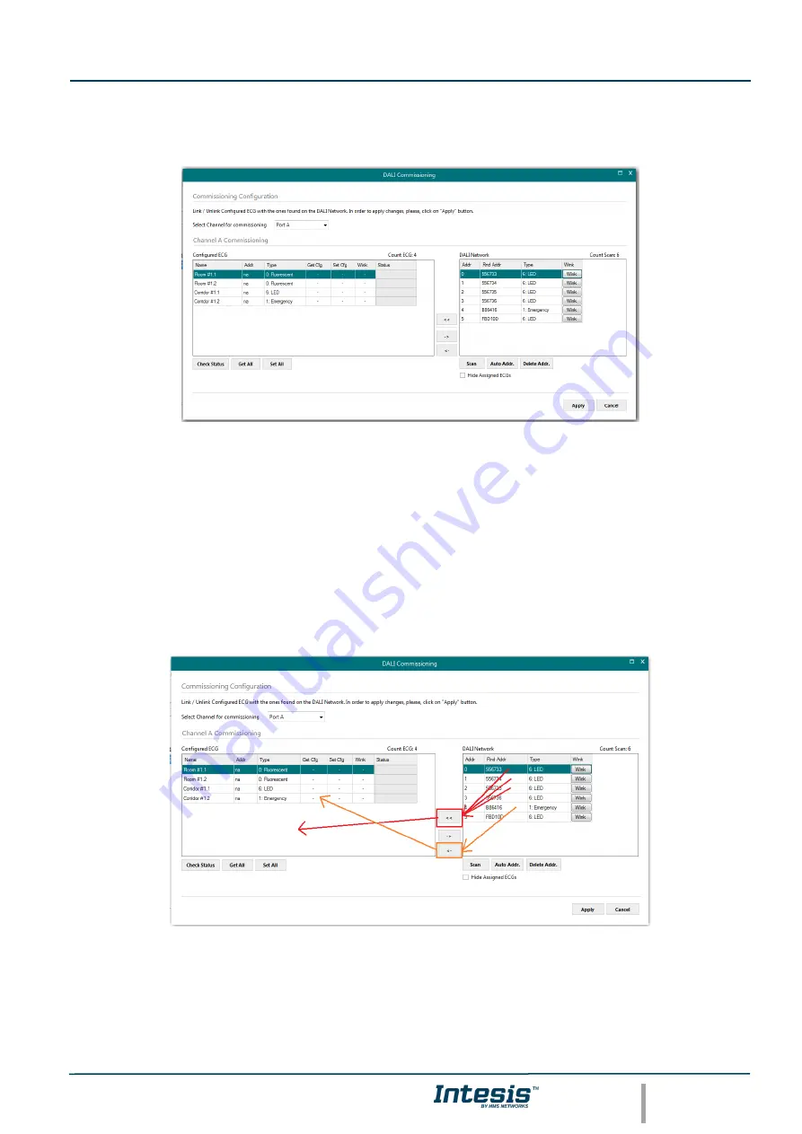
Figure
A.11
Functionality of ‘<<’ and ‘<-‘ buttons
In Figure’s example, we’ll associate LED ballasts with short addres 0, 1 and 2 and Emergency light with short address
5 to existing ballasts (with ‘<-‘ button), and add ballasts from short addresses 3 and 4 as new ballasts in the
configuration.