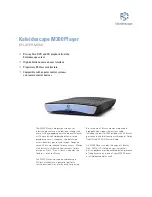
background image

8

OBD2 Harness

Power Socket

Harness

Power Supply

Harness

Splice to the constant

power supply wire.

Do not connect when the

self-diagnosis connector

is not available.

Yellow Wire

Yellow Wire

Black Wire

White Wire

White/Black Wire

Pink Wire

Wiring for BMW

 White Connector

6      7                   10

10

Cut the #10 wire.

Insulate with

electrical tape.

6      7                   10

(1) Connect the vehicle's on-board monitor and CAMP2 using the AV cable.

   Advice


If the on-board monitor needs a special connector or another harness available from the

     monitor's manufacturer, this must be used.

(2) Connect the remote controller receiver harness to CAMP2.

(3) Connect the relay harness to CAMP2.

(4) Connect the white connector of the OBD2 to the relay harness.

   Advice 


For non Nissan vehicles, connect the White/Black wire of the car

     plug harness to the pink wire of the OBD2 harness. 


If a 12V power socket the cigar socket is not available, connect the

     power supply harness to the pink wire of the OBD2 harness.

     Splice these to the line that outputs 12V while ignition is on.

     (See page 10 for splicing.)


For BMW, cut the wire inserted into #10 of the white connector. 

     (See the illustration on the right.)  Insulate both ends of the cut wire

     with electrical tape to prevent shorts.  Connect the power supply harness

     to the pink wire of the OBD2 harness.  Splice these to the line that 

     outputs 12V while ignition is on.  (See page 10 for splicing.)

(5) Connect the red connector of the OBD2 harness to the vehicle's self-diagnosis connector.

(6) Insert the battery into the remote controller.

     (For replacing the button battery, see Maintenance in page 29.)

F-CON Wiring

<When the vehicle's self-diagnosis connector (OBD2 port) is unused (available)>

(1) Follow the procedure (1) to (6) above.

(2) Connect the F-CON connector of CAMP2 to the option port of the F-CON unit with the modular

     cable.

   NOTE 


The modular cable is not included.  Use the optional F-CON connecting cable or a 6 pin - 4

     core straight modular cable available at a hardware store. 

(3) Connect the OBD2 harness as shown below.


Connect the white/black wire of the power socket harness to the pink wire of the OBD2 harness.

     Connect the black wire of the power socket harness to the white wire of the OBD2 harness.


Connect the yellow wire of the OBD2 harness to the power supply harness.  Splice these to

     the line that outputs 12V while ignition is off (constant power supply).  (See page 10 for splicing.)
(When the vehicle's self-diagnosis connector is being used (NOT available))

Summary of Contents for CAMP2

Page 1: ...INSTRUCTION MANUAL E84511 K00070 00 2008 1 Ver 3 1 01 HK S E L E C T R ONIC S T E C HNOL OG Y ...

Page 2: ......

Page 3: ...pes of Displayable Data Up to 6 of the following 24 data items can be displayed on the screen at one time Speed Engine RPM Water Temperature Ignition Timing A F Correction Value A F Learning Value Intake Air Volume Intake Temperature Throttle Position Intake Manifold Pressure O2 Voltage Airflow Voltage Fuel Injection time Battery Voltage Fuel Efficiency Horsepower A F Value Knocking Value I F Boos...

Page 4: ...responsible for any damage caused by removing vehicle s in exterior electric parts or modification for installation This product was designed based on installing it onto a factory vehicle or a vehicle using other HKS products The performance and or safety cannot be guaranteed if this product was installed onto other inapplicable vehicles This product works only with a vehicle with DC12V negative g...

Page 5: ...is product by yourself unless you have and know how to use the tools and equipment necessary to safely perform service operations on your vehicle Do not modify disassemble and or remodel the product and attached parts to avoid any damage to the unit and or harness Handle the parts with caution at all times To avoid possible malfunction and damage to the engine install the unit away from excessive ...

Page 6: ...IST Instruction Manual Double sided Tape Remote Controller Receiver CAMP2 1 1 1 1 1 1 1 3 2 3 4 5 8 9 10 11 12 1 5m Power Socket Harness 1 OBD2 Harness 0 3m Power Supply Harness AV Cable 1 1 1 0m 6 7 1 Remote Controller Velcro Tape Black 2 0m Tie Wrap 2 Black 13 Splice 14 1 1 0m 2 0m 車種 別適 合表 本書は HKS CAM P2を 取付け るため の適合 表です 製品の 取付け は取扱 説明書 をお読 みくだ さい 取付け る車両 の車種 年式 型式 エン ジン型 式 通 信タイ プ コネク タ位置 をよく ...

Page 7: ...s is to connect CAMP2 to F CON using a modular cable 4 I F Unit Connector This is to connect a meter harness to use HKS I F Unit P N 44008 AK011 with CAMP2 5 Video Signal Output Terminal Yellow This is to connect the yellow AV cable to output video to the screen 6 Audio Signal Output Terminal White 7 Audio Signal Output Terminal Red This is to connect the white and red AV cable to output audio to ...

Page 8: ...re I F Unit s Oil Temperature I F Unit s Oil Pressure I F Unit s Fuel Pressure I F Unit s EGT 1 2 3 4 5 6 7 8 9 10 11 12 13 14 15 16 17 18 19 20 21 22 23 24 25 Unit SI km h rpm CA g s 100kPa V V ms V km L kW 100kPa 100kPa 100kPa USA mph rpm F CA g s F PSI V V ms V m USG HP PSI F F PSI PSI F 1 PEAK Button Press this button to show the peak value 2 Directional Arrow Buttons 4 Press these directional...

Page 9: ...wire Yellow Wire Pink Wire Power Supply Harness OBD2 Harness BMW Standard Vehicle This manual shows a typical installation Actual installation may vary depending on the vehicle application This product is for vehicles that operate on a DC12V negative ground Do not install onto any vehicle operates on a DC24V it may cause a fire Connect the OBD2 Cable Remote Controller Receiver Relay Harness To the...

Page 10: ...ustration on the right Insulate both ends of the cut wire with electrical tape to prevent shorts Connect the power supply harness to the pink wire of the OBD2 harness Splice these to the line that outputs 12V while ignition is on See page 10 for splicing 5 Connect the red connector of the OBD2 harness to the vehicle s self diagnosis connector 6 Insert the battery into the remote controller For rep...

Page 11: ...T TEMP OIL PRESS BOOST VACUUM FUEL PRESS I F Unit Main Harness Power Supply Harness Meter Harness 1 White Orange Red Black Connect sensor harnesses Engine Room Interior If the meter harness 1 length is too short to reach CAMP2 use the optional meter harness 3 1 0m to connect CAMP2 and the meter harness 1 To Constant Power Supply wire To IG wire To illumination wire Body ground ...

Page 12: ...s list Splicing Strip 5mm of the wire cover for wiring as shown to the right Connect another wire to the uncovered portion twisting wires together Crimp the twisted wires using a splice Cover the splice and wires with electrical tape to insulate 1 Mount the CAMP2 main unit using the Velcro tape on the area where the controller receiver is reachable and away from exposure to the direct rays of the ...

Page 13: ...the following Check item Make sure all wiring is done correctly Make sure all installed components do not come in contact with other parts Make sure harnesses are secured so that they do not disturb driving Make sure all removed factory parts are reinstalled Make sure the negative cable terminal is securely connected to the battery Make sure a battery is set to the remote controller Advice Do not ...

Page 14: ...ers Switch by the enter button 1analog meter 6 digital meters ANALOG SELECT ANALOG 1 6 METER COLOR DIGITAL METER S E L E C T B A C K S D F PAST 6 items can be shown TIME Elapsed Time DISTANCE Distance Driven SPEED Average speed FUEL Fuel consumption ECO Average fuel efficiency COST Fuel cost Channel is selectable from A to D Under channel A the automatic measurement is available in SET UP Mode MEN...

Page 15: ...2 X OFFSET Y OFFSET UNIT TITLE BACK MENU BACK EDIT RED EDIT GREEN EDIT BLUE S D F Manufacturer name Fuel efficiency correction value Speed correction value Horsepower correction value Vehicle weight Gasoline cost Auto PAST function ON OFF Warning setting Reset Go to the next page Go back to the previous page Adjusting the video position left Adjusting the video position up Unit of measure Switch S...

Page 16: ...tank on level ground Set PAST mode to CLEAR START Drive until the fuel tank becomes nearly empty and fill up the tank at the same location in Calculate the actual ECO CORRECT value from the fuel volume and the FUEL value in PAST mode Actual ECO CORRECT Set Value Fuel Volume FUEL value 1000 Setting In the menu use the direction button in the controller to select SET UP and press the ENTER SET UP me...

Page 17: ... correction value by measuring the actual driving distance as follows Do not measure on a public road Do not burn out or otherwise spin tires without contact with pavement while measuring Measure while the vehicle is driven in a straight line Measurement needs a certain distance to figure out the actual driving distance SPEED CORRECT Speed correction value Actual driving distance the indicated DIS...

Page 18: ...alf the fuel tank representing total weight of fuel oils coolant etc GAS COST Fuel cost USG This item is to enter the fuel cost The set value range is from US 1 50 to 10 0 in increments of US 0 01 COST in PAST mode is calculated from this value The default value is US 1 50 AUTO PAST Automatic past function This item is to activate PAST mode Channel A automatically when the ignition is turned on AU...

Page 19: ... HP SI Unit Distance km Speed km h Fuel volume L Temperature C Fuel Efficiency km L Pressure x 100kPa Horse Power kw Other items use common units TITLE BACK Menu s background color Select the color of Menu s background The default color is blue BLUE BLACK MENU BACK Each item s background color Select the color of the items background The color selected here is the color of all items The default co...

Page 20: ... from A to D using the controller s directional arrow buttons Advice All 4 channels can measure at the same time The encircled letter tells which channel is currently active on the screen To change the channel press the red cursor Operation Start Measurement Select START using the controller s directional arrow buttons Press ENTER Stop Measurement Select STOP using the controller s directional arr...

Page 21: ...troller s directional arrow buttons Press ENTER When the characters color changes to white setting changes can be made When NONE appears no item is available to be shown If more than one item needs to be edited repeat the above procedure ENDLESS LOGGING Setting logging Sets the logging to function endlessly in a loop up to 10 minutes per loop ENDLESS LOG OFF ENDLESS LOG ON After changing the setti...

Page 22: ...ivated the color of the value is changed from white to red and the buzzer sounds For setting of this function see the warning setting under the SET UP mode Advice WARNING functions only for the item on the screen To see other items warning setting first select the desired item to be shown on the screen If selecting the same item the same data is shown on each screen When the ignition is turned off...

Page 23: ...it select 1 from a possible 25 items using the directional arrow buttons Press ENTER When the character color changes from orange to white the edit is complete When NONE appears it means that there is no item to show ANALOG 1 appears on the left 2 in the center 3 on the right If more items needed to be edited repeat the procedure above Advice Only ANALOG 1 to 3 can be shown on the screen as the an...

Page 24: ...ange to white the edit is complete When NONE appears it means that there is no item to show If more items needed to be edited repeat the procedure above Advice ANALOG 1 appears as the analog meter and ANALOG 1 to 6 are to be shown as digital meters below the analog meter 6 digital meters on the screen shows ANALOG 1 to 3 from upper left hand side and ANALOG 4 to 6 from lower left hand side METER C...

Page 25: ...e peak values are shown Advice The color of the peak value in the analog meter will not be changed Reset Peak Value Press ENTER on the controller to reset the peak value Exit Peak Indication Press the BACK button of the controller to exit WARNING Indication When the warning function is activated the color of the warning indicator in the analog meter is changed to red the values of the digital mete...

Page 26: ... right illustration above DIGITAL 1 6 Selecting items to indicate To change individual settings select from DIGITAL 1 6 using the directional arrow buttons Press ENTER After the character color changes from white to orange the setting can be edited To edit select 1 from a possible 25 items using the directional arrow buttons Press ENTER When the character color changes from orange to white the edi...

Page 27: ...ital bar graphs by pressing ENTER The bar graph consists of 20 bars Real time values and Peak values are shown on the screen PEAK Indication Peak Value Indication Pressing the Peak button of the controller turns on the peak indicator in the digital meter in green Also the color of the values in the digital meter changes from white to green and the peak values are shown Reset Peak Value Press the E...

Page 28: ... Y axis Engine Load 16 Setting From the menu select F CON using the directional arrow buttons Press ENTER Press the directional arrow buttons of the controller to select the map to correct Press ENTER when the red cursor points to the desired map The screen will switch to the correction map The right illustration above Editing the Correction Map Move the green cursor to the setting position using ...

Page 29: ...correction map The 6 digital meter items on the right are monitoring values from the F CON sensors current input values These items cannot be edited since they are taken from the output signal from F CON Advice Turn off the ignition when connecting the F CON otherwise the CAMP2 unit may become damaged Editable correction maps may vary depending on the dip switch settings on the F CON and or the HK...

Page 30: ... Pressure Sensor Harness Sealing Tape EGT Sensor EGT Sensor Harness Fitting I F Unit Main Harness Power Harness Meter Harness No 1 L 30cm Proper daily maintenance of this product is necessary in order to maintain the safety reliability and function of this product ATTENTION Maintenance is the responsibility of the driver owner Before handling the unit the controller and the receiver clean your han...

Page 31: ...lide switch position Connectors not connected properly Improper wire splicing Incorrect setting value under SET UP MODE Connectors not connected properly Improper wire splicing Dead battery or not set properly The receiver is not connected properly or not in a position to receive signals from the controller Connect the AV cable Start the engine Turn on the monitor or the car navigation Replace the...

Page 32: ...Pursuing the Ultimate in Engine Performance and Efficiency H K S Company Limited ...

Reviews: