HITEC OPTIC 6 Sport Instruction Manual Download Page 29

Page  55

Page 56

Your Optic 6 Sport 2.4’s system's HELI menu provides three flight modes in addition to the normal one (NOR). Within each condition, 
you may program an independent set of dual rates, exponentials, throttle and pitch curves, revolution mixing, and gyro gain. 
In the HELI menus, these are automatically called up whenever you switch to a new condition. 
NOR is intended for hovering flight. ST1 may be used for forward flight and mild aerobatics, ST2 may be used for inverted, and ST3 is used 
for autorotations as it includes a throttle hold feature which disengages the throttle servo from collective commands. 
These conditions are activated whenever the model memory is chosen to be HELI type

The defaults for the switches controlling these flight conditions are as follows:

SWAH (120 Swash Plate Programming)

OPTIC 6 SPORT ACRO DATA SHEET

FLT. C (Flight Conditions or "Idle-Up's")

4. Call up the swash screen by repeatedly pressing one of the Up Down EDIT buttons until the SWAH 
    window appears. 
    The function is automatically active when you select 120  mixing in the model setup menu.
5. If all the servos raise the swash with increasing collective, go to the next step. If they lower the swash, 
    press the CURSOR Right button twice to get to the collective setting menu 
    (the arrow appears over the number 6). 
    Now press the DATA “-” button until the sign is reversed in front of the percentage value. 
    Now the swash should properly respond to collective. 
    If you've done the wrong thing, you can reset the percentage by pressing the Active/Inhibit (Clear) button.
6. If all the servos tilt the swash to the right with right aileron stick, go to the next step. 
    If they tilt the swash to the left, press the CURSOR Right button once to get to the aileron setting menu 
    (the arrow appears over the number 1).
    Reverse the sign in front of the percentage with the DATA “-” button. Now the swash should properly respond to aileron.
7. If all the servos tilt the swash aft with up elevator stick, go to the next step. 
    If they tilt the swash forwards, press the CURSOR Right button once to get to the elevator setting menu 
    (the arrow appears over the number 2). 
    Now press the DATA “-” button until the sign is reversed in front of the percentage value. 
    Now the swash should properly respond to elevator.
8. Double check that all three functions, collective, aileron, and elevator, produce the desired result on the swashplate.
    Do not set any SWAH values to 0% or you will disable the response to that control!

FLT. C  (Flight Conditions or "Idle-Up's")

- NOR: ON when Flt. Mode (SW-3) Switch is BACK.
- ST1: ON when Flt. Mode (SW-3) Switch CENTER.
- ST2: ON when Flt. Mode (SW-4) Switch is FORWARD
- ST3: ON when SW-1 is DOWN. (For Throttle Hold only)

As these functions are switched on or off, ST3 = HOLD has 
highest priority, followed by ST2 and ST1. Regular settings (NOR)
occur when all of the others are off. 

Throttle and pitch curves, revolution mixing, and gyro gain may 
be independently selected for each condition.

Here are some suggested starting settings if your instructions do 
not provide any:

Point       1 (low)  

    2   

    3   

     4  

5 (high)

  %  

   20 

   38  

   50  

   75  

    100

Throttle Curve 

ST2

Throttle Curve 

ST1

Point  

1 (low)  

    2   

    3   

     4  

5 (high)

  %  

 100  

   50  

   38  

    50  

   100

Pitch Curve 

ST1

Point  

1 (low)  

    2   

    3   

     4  

5 (high)

Pitch  

-4 deg.    +0.5  

  +6.0  

  +7.5  

   +9.0

Pitch Curve 

ST2

Pitch Curve 

ST3

 (

HOLD

)

Point  

1 (low)  

     2   

    3   

     4  

5 (high)

Pitch  

-9 deg.     -6.0  

    0  

   6.0        9 or 10.0

Point       1 (low)  

    2   

     3   

     4  

5 (high)

Pitch       - 4 deg.      --  

  + 6.5  

     --  

 +12

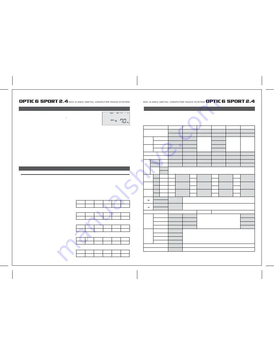
MODEL  TYPE : ACRO     SFT : N , P                


MODEL NAME : 0       1       2       3      4       5       6       7       8       9      .                     

*Please make a copy and fill this form out. 

CH1 CH2  CH3 CH4  CH5  CH6 

NOR , REV 

NOR , REV 

NOR , REV 

NOR , REV 

NOR , REV 

NOR , REV  

EPA 

PMX

CUT

L/U 

 %  L/U 

%  L/U 

%  L/U 

L/U 

 %  L/U 

R/D % 

R/D % 

R/D  % 

R/D % 

R/D % 

R/D % 

MAS

SLV

ON

OFF

STICK

SERVO

STICK

SERVO

STICK

SERVO

ON

INH

ON

INH

ON

INH

ELVN 


FLPN 


V.TAL 


A R 


E F 

ON 

INH 

ON 

INH 

NOR 

ST1 

ST2 

ST3 

NOR 

ST1 

ST2 

ST3 

ON 

ON , OFF 

ON , OFF 

ON , OFF 


1  ,  2 

TIMER   

MODE   

CAMB 


FLT.C 


ON 

INH 

TRM 

D/R 


EXP 

S.TRM   

S.REV   

%

%

%

%

%

%

%

%

%

%

%

%

%

%

%

%

%

% %

%

%

%

AILE

CH1

AILE

CH1

ELEV

CH2

AILE

CH2

AILE

CH6

ELEV

CH4

ELEV

CH2

FLAP

CH6

RUDD

CH4

ELEV

CH1

FLAP

CH1

RUDD

CH2

*Each flight condition for D/R & EXP are not shown on the chart.

Summary of Contents for OPTIC 6 Sport

Page 1: ...AL COMPUTER RADIO SYSTEM SYSTEM 2 4 Function Assignable Switches Easy to Read LCD Screen Bulit in Hitec AFHSS 2 4GHz System INSTRUCTION MANUAL 0678 6CH 2 4GHz DIGITAL COMPUTER RADIO SYSTEM 2 4 Made in...

Page 2: ...C 6 SPORT 2 4 is your first programmable radio control transmitter you re probably feeling a bit overwhelmed by all the buttons and switches on the case and the cryptic symbols that appear on the radi...

Page 3: ...emperature extremes For protection wrap the receiver in the provided Flight Preserver foam rubber or use some other vibration absorbing materials If your flying near bodies of water it s also a good i...

Page 4: ...ally power on the STUDENT transmitter Though it is powered on the STUDENT transmitter will not transmit the radio signal as long as the trainer cable is connected properly 1 To use the trainer system...

Page 5: ...n their vicinity Flying Safety Stick Length Adjustment You may adjust the stick tension of your sticks to provide the feel that you like for flying To adjust your springs you ll have to remove the rea...

Page 6: ...of using this function whenever you are carrying your model to the flight line LOCK button KEEP YOUR HANDS AWAY FROM THE PROPELLER OR ROTORS EVEN AFTER ENABLING THE LOCK FUNCTION A RADIO GLITCH COULD...

Page 7: ...with Dual LED indicator has two colored LEDs blue and red for status indication and for set up process indication of 2 4GHz system This function button can be used for Link ID Setting process between...

Page 8: ...on is easy and simple insert the antenna into the supported Antenna holder and stick it to the desired spot you wish to install Optima 6 Receiver Features Optima Receiver Connection Diagrams Follow th...

Page 9: ...e are available 2 4GHz channels that can be used by your Hitec AFHSS 2 4 system The following will explain how Normal Mode and Scan Mode use the channels Normal Mode In this mode the receiver transmit...

Page 10: ...switch to Scan Mode noted by the blue and red LED and one beep Switching from Normal Mode to Scan Mode 1Sec 3Sec 3Sec Turn on transmitter then the receiver You will hear two short beep sound for Scan...

Page 11: ...ivers into other aircraft to be controlled by your Aurora Note both module and receiver need to re boot turn the power off and back on FAIL SAFE and Hold Mode FAIL SAFE Setup If you use the FAIL SAFE...

Page 12: ...a regulator set up or a commercially available BEC with enough capacity 3A or more capacity is recommended The SPC system was partially created to be integrated into future Hitec telemetry system devi...

Page 13: ...symbol in the black box at the bottom of the screen indicates which switch SW1 or SW3 needs to be reset to Normal Rx Ch ACRO GLID HELI Aileron Aileron Roll Cyclic One or Right Flaperon FLPN ON or Rig...

Page 14: ...information on using the timer function Otherwise move down to the next menu item 5 Select the control s Mode configuration 6 Select the signal shift Under the word MODE the number 2 is blinking by d...

Page 15: ...itial setup menu Go ahead and switch the transmitter on you are now in the standard operating screen In the upper left hand corner it will say ACRO and to the right there will be a large number tellin...

Page 16: ...direction The EPA function is normally used to prevent any servos from binding at the ends of their travel 1 To set the RIGHT TURN aileron motion which is upward on the right wing and downward on the...

Page 17: ...blinking if it isn t already by default The default value showing on the screen should be 100 but notice the extra little zero next to the 100 This indicates that the rate is this value 100 when the s...

Page 18: ...o servos simultaneously This is especially useful if you are using two elevator servos one to each half of the elevator In flight if the elevator needs to be trimmed you can make the adjustment with t...

Page 19: ...a rudder control to the aileron stick movement refer to the Aileron Rudder mix on page 26 Use a small percentage of mix for coordinated turns or set it up at 100 mix if your plane does not have ailero...

Page 20: ...buttons simultaneously Now we are ready to feed in values for the ailerons and elevator for pitch compensation when you pull the switch toward you You could of course choose to activate the mode with...

Page 21: ...der the default value of 100 If it isn t you can return to the default value immediately by pressing the Clear button Next to the 100 a 0 indicates that switch SW 2 is in the 0 position if it isn t pu...

Page 22: ...back to this section when you are ready to begin the setup 1 Start with the correct model type GLID in the Initial Setup Menu 2 Access the main programming menu then use the REV function and make sure...

Page 23: ...ints inside circle Too much coupling or differential Reduce one or both ADIF Aileron Differential Initial Menu Feature Review for GLID Programming The following item is located in the Initial Menu as...

Page 24: ...on CH 6 to 75 of their travel If you have two flap servos they should be connected with a Y harness to the channel 6 slot on the receiver 4 Finally curser to CH 2 and set the elevator travel value so...

Page 25: ...smitters in the gyro s manual 7 Program 35 EXPO values for Roll Ch 1 and Pitch Ch 2 8 After your heli is all ready to fly put it on a shelf and go get an R C flight simulator program for your PC Spend...

Page 26: ...this menu you can program specific control functions and the value the amount of servo travel for the particular model helicopter you selected earlier in the initial setup menu Go ahead and switch th...

Page 27: ...ttle hold 3 You begin a point 1 which will be blinking This is the idle position and will have a default value of 0 Press the DATA Increase or Decrease button to change the setting to your desired val...

Page 28: ...type does contain the SWAH menu The swash default settings are shown below The Throttle Hold function moves the engine throttle servo to a selected position near idle and disengages it from the throt...

Page 29: ...aileron 7 If all the servos tilt the swash aft with up elevator stick go to the next step If they tilt the swash forwards press the CURSOR Right button once to get to the elevator setting menu the arr...

Page 30: ...E CH5 ON INH ON INH ON INH NOR ST1 ST2 ST3 V TAL A R E F CROW CAMB ADIF FLT C TIMER MODE ON INH TRM 0 1 0 1 D R EXP S TRM S REV ELEV CH2 ELEV CH4 RUDD CH4 RUDD CH2 MODEL TYPE HELI SFT N P MODEL NAME 0...

Reviews: