HITEC OPTIC 6 Sport Instruction Manual Download Page 11

Page 19

Page 20

Optima Series Receiver Features and setup

Optima Series Receiver Features and setup

Set-up and Use of  the Hitec 2.4GHz System

Always do a pre-flight function check

Before the engine or motor is started, turn on the system as explained above. Then make sure all the servos and control surfaces are
working properly. If any control surface is not moving properly, do not fly the aircraft until the problem is solved.
Range Check
Do a complete range check as described on page 18 before each flying session to confirm the radio system is working properly.
Your Hitec AFHSS system uses a communication protocol that links and binds the Optima receiver to your Aurora transmitter. Once their
ID is set, no other transmitter can interfere with your receiver during its operation. In the case of multiple model memory transmitters like
Aurora 9, you can bind or link as many Optima receivers to your transmitter as necessary.

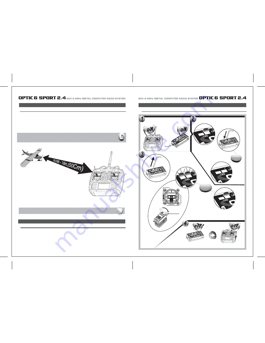
- Binding must be done within 15ft. (5m) of the transmitter and receiver.
- Transmitter and receiver need to be at least 18in. (45cm) from each other to binding properly.
- In the ScanMode, if the transmitter or receiver has been shut off or disconnected for more than one second,

note : Each system and module / receiver set is paired at the factory for your convenience. 
          Use the following Link (ID-Setting)
          sequence as you add Optima receivers into other aircraft to be controlled by your Aurora.

Note : both module and receiver need to re-boot (turn the power off, and back on).

FAIL-SAFE and Hold Mode

FAIL-SAFE Setup

If you use the FAIL-SAFE function, and set it up properly, should the receiver signal somehow be interrupted or interference were to occur, 
the servos will move to your pre-set FAIL-SAFE point you previously stored in the receiver during the FAIL-SAFE set-up process.
If FAIL-SAFE has not been activated, the signal is switched off after the HOLD period of 1 sec. This means that the servos become “soft” and 
remain in their last commanded position under no load (this may equate to full-throttle!), until a valid signal is picked up again.
In the interests of safety, we recommend that FAIL-SAFE should always be activated, and the FAIL-SAFE settings should be selected so as 
to bring the model to a non-critical situation (e.g. motor idle / electric motor OFF, control surfaces neutral, airbrakes extended, aero-tow 
release open, etc).

6Sec.

5Sec.

Fail-Safe position

Switch on both. 
Wait for the system to boot and control over the model.

Press and hold the button on the Optima until LED turns off
 (approx. 6 second)

Release the button. After 2 seconds both red and blue LEDs blink rapidly.
the receiver will count 5 seconds during that time move all the transmitter 
sticks and other controls to the desired FAIL-SAFE positions 
(e.g. motor idle, control surfaces neutral), and hold  until blink stops.

When Blink stops the system will temporary remember the FAIL-SAFE position, turn off the system to save.

Summary of Contents for OPTIC 6 Sport

Page 1: ...AL COMPUTER RADIO SYSTEM SYSTEM 2 4 Function Assignable Switches Easy to Read LCD Screen Bulit in Hitec AFHSS 2 4GHz System INSTRUCTION MANUAL 0678 6CH 2 4GHz DIGITAL COMPUTER RADIO SYSTEM 2 4 Made in...

Page 2: ...C 6 SPORT 2 4 is your first programmable radio control transmitter you re probably feeling a bit overwhelmed by all the buttons and switches on the case and the cryptic symbols that appear on the radi...

Page 3: ...emperature extremes For protection wrap the receiver in the provided Flight Preserver foam rubber or use some other vibration absorbing materials If your flying near bodies of water it s also a good i...

Page 4: ...ally power on the STUDENT transmitter Though it is powered on the STUDENT transmitter will not transmit the radio signal as long as the trainer cable is connected properly 1 To use the trainer system...

Page 5: ...n their vicinity Flying Safety Stick Length Adjustment You may adjust the stick tension of your sticks to provide the feel that you like for flying To adjust your springs you ll have to remove the rea...

Page 6: ...of using this function whenever you are carrying your model to the flight line LOCK button KEEP YOUR HANDS AWAY FROM THE PROPELLER OR ROTORS EVEN AFTER ENABLING THE LOCK FUNCTION A RADIO GLITCH COULD...

Page 7: ...with Dual LED indicator has two colored LEDs blue and red for status indication and for set up process indication of 2 4GHz system This function button can be used for Link ID Setting process between...

Page 8: ...on is easy and simple insert the antenna into the supported Antenna holder and stick it to the desired spot you wish to install Optima 6 Receiver Features Optima Receiver Connection Diagrams Follow th...

Page 9: ...e are available 2 4GHz channels that can be used by your Hitec AFHSS 2 4 system The following will explain how Normal Mode and Scan Mode use the channels Normal Mode In this mode the receiver transmit...

Page 10: ...switch to Scan Mode noted by the blue and red LED and one beep Switching from Normal Mode to Scan Mode 1Sec 3Sec 3Sec Turn on transmitter then the receiver You will hear two short beep sound for Scan...

Page 11: ...ivers into other aircraft to be controlled by your Aurora Note both module and receiver need to re boot turn the power off and back on FAIL SAFE and Hold Mode FAIL SAFE Setup If you use the FAIL SAFE...

Page 12: ...a regulator set up or a commercially available BEC with enough capacity 3A or more capacity is recommended The SPC system was partially created to be integrated into future Hitec telemetry system devi...

Page 13: ...symbol in the black box at the bottom of the screen indicates which switch SW1 or SW3 needs to be reset to Normal Rx Ch ACRO GLID HELI Aileron Aileron Roll Cyclic One or Right Flaperon FLPN ON or Rig...

Page 14: ...information on using the timer function Otherwise move down to the next menu item 5 Select the control s Mode configuration 6 Select the signal shift Under the word MODE the number 2 is blinking by d...

Page 15: ...itial setup menu Go ahead and switch the transmitter on you are now in the standard operating screen In the upper left hand corner it will say ACRO and to the right there will be a large number tellin...

Page 16: ...direction The EPA function is normally used to prevent any servos from binding at the ends of their travel 1 To set the RIGHT TURN aileron motion which is upward on the right wing and downward on the...

Page 17: ...blinking if it isn t already by default The default value showing on the screen should be 100 but notice the extra little zero next to the 100 This indicates that the rate is this value 100 when the s...

Page 18: ...o servos simultaneously This is especially useful if you are using two elevator servos one to each half of the elevator In flight if the elevator needs to be trimmed you can make the adjustment with t...

Page 19: ...a rudder control to the aileron stick movement refer to the Aileron Rudder mix on page 26 Use a small percentage of mix for coordinated turns or set it up at 100 mix if your plane does not have ailero...

Page 20: ...buttons simultaneously Now we are ready to feed in values for the ailerons and elevator for pitch compensation when you pull the switch toward you You could of course choose to activate the mode with...

Page 21: ...der the default value of 100 If it isn t you can return to the default value immediately by pressing the Clear button Next to the 100 a 0 indicates that switch SW 2 is in the 0 position if it isn t pu...

Page 22: ...back to this section when you are ready to begin the setup 1 Start with the correct model type GLID in the Initial Setup Menu 2 Access the main programming menu then use the REV function and make sure...

Page 23: ...ints inside circle Too much coupling or differential Reduce one or both ADIF Aileron Differential Initial Menu Feature Review for GLID Programming The following item is located in the Initial Menu as...

Page 24: ...on CH 6 to 75 of their travel If you have two flap servos they should be connected with a Y harness to the channel 6 slot on the receiver 4 Finally curser to CH 2 and set the elevator travel value so...

Page 25: ...smitters in the gyro s manual 7 Program 35 EXPO values for Roll Ch 1 and Pitch Ch 2 8 After your heli is all ready to fly put it on a shelf and go get an R C flight simulator program for your PC Spend...

Page 26: ...this menu you can program specific control functions and the value the amount of servo travel for the particular model helicopter you selected earlier in the initial setup menu Go ahead and switch th...

Page 27: ...ttle hold 3 You begin a point 1 which will be blinking This is the idle position and will have a default value of 0 Press the DATA Increase or Decrease button to change the setting to your desired val...

Page 28: ...type does contain the SWAH menu The swash default settings are shown below The Throttle Hold function moves the engine throttle servo to a selected position near idle and disengages it from the throt...

Page 29: ...aileron 7 If all the servos tilt the swash aft with up elevator stick go to the next step If they tilt the swash forwards press the CURSOR Right button once to get to the elevator setting menu the arr...

Page 30: ...E CH5 ON INH ON INH ON INH NOR ST1 ST2 ST3 V TAL A R E F CROW CAMB ADIF FLT C TIMER MODE ON INH TRM 0 1 0 1 D R EXP S TRM S REV ELEV CH2 ELEV CH4 RUDD CH4 RUDD CH2 MODEL TYPE HELI SFT N P MODEL NAME 0...

Reviews: