


Page 53
Page 54
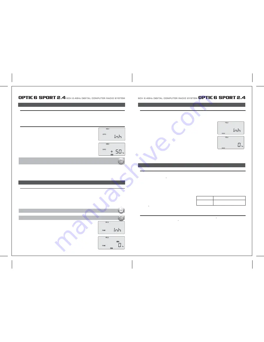
HOLD (Throttle Hold)
RVMX (Revolution Mix)
The revolution mixing function mixes pitch commands to the tail rotor in order to suppress the torque generated by changes in the main
rotor's pitch angle and rotational speed.
You can input independent values for revolution mixing above and below one-half throttle for each of the NOR, ST1, and ST2 flight conditions.
Revolution mixing is disabled whenever throttle hold (ST3, operated by switch SW -1) is on.
For a clockwise-turning rotor, revolution mixing should apply right rudder when pitch is increased; for a counterclockwise turning rotor, the
opposite should occur. Remember to set the value for both sides of the throttle stick's motion.
Revolution mixing has no preprogrammed values input at the start. You will need to input values for your helicopter as described in the setup
example.
1. Call up the revolution mixing screen by repeatedly pressing one of the Up Down EDIT buttons until
the RVMX window appears. The function is active with 0% mixing turned on.
Put the throttle stick to its idle position.
2. Now press the DATA “+” button.
This will increase the percentage of RVMX mixing for the low side of throttle.
You may set a value of 0% to 100% for this side. If you wish to return the mixing percentage to
the default 0% value, press the Active/Inhibit (Clear) button.
3. Move the throttle stick to a position above half-throttle, and change the percentage number to suit.
4. Now verify that the rudder responds both the correct direction and amount for travel on both sides
when throttle is commanded.
5. Set up the RVMX values for the other flight conditions (ST1, ST2) by flipping the Flt. Mode (SW-3)
switch and repeating these procedures.
GYRO (Gyro Gain)
Gyro settings are used to automatically control the gyro's gain in all 4 different flight modes. It may be set to different values in NOR, ST1, ST2,
and ST3 flight modes, allowing you to pick the gain you need for each circumstance.
The Gyro settings control the output at receiver CH5. You cannot independently control this channel with a switch.
There are many manufacturers of gyros. Not all of their setup are the same.
Read your gyro manual for a full understanding on its installation and setup.
Using Gyro Settings
1. Press one of the “Up”, “Down” EDIT buttons repeatedly to get to the GYRO menu.
To begin with, the function is inhibited.
Press one of the CURSOR buttons to activate it. Once activated, it's set to 50% in all four flight modes.
GYRO (Gyro Gain)
The Swashplate menu is intended only for helicopters whose collective pitch is controlled by more than a single servo at a time,
and is sometimes referred to as CCPM (Collective & Cyclic Pitch Mixing).
The Optic contains settings for 120 swashplates.
Consult your model's setup instructions to find out whether you need special swash settings.
The swashplate menu is used to control the response of all three collective servos as a group.
It should NOT be used for reversing or individual servo travel adjustment. Perform these settings in the REV and EPA menus respectively.
When you move the collective stick, all swash plate servos should move in the same direction with the same amount of up and down travel
without tilting the swash plate. If the swashplate should tilt to one side when you command collective, one or more servos is moving the
wrong direction or the wrong amount, and must be adjusted in the SWAH menu.
If the swashplate moves down when pitch should be increasing or vice
versa, change the sign in front of all three servos from (+) to (-) or vice
versa.
Note that there is no SWAH menu when the NOR menu is selected,
but the 120 swash type does contain the SWAH menu.
The swash default settings are shown below.
The Throttle Hold function moves the engine throttle servo to a selected position near idle, and disengages it from the throttle stick.
It is commonly used during autorotation, and activated with the SW-1 switch on the left front of the transmitter.
You can set the throttle position to be held over a -25 to +100% range centered about the throttle idle position.
Activating throttle hold also disables revolution mixing (RVMX).
1. Press one of the “Up”, “Down” EDIT buttons until the HOLD window appears.
The default is for the function to be inhibited.
To activate the throttle hold function, press both DATA buttons at the same time.
This will cause the flashing INH display to change to a 0% value.
3. Check that your throttle goes to the desired hold position by flipping the SW-1 switch one way and the other.
Adjust the number as needed. Be sure to choose an engine speed that's fast enough to keep the engine from accidentally quitting,
but slow enough to not engage the main rotor clutch.
1. Consult your model's setup instructions. If three servos are needed to move the swashplate in a 120 CCPM set-up, go to the model
setup instructions on page 37 and select the 120 swash type.
2. With all the servos hooked up, and the transmitter and receiver turned on, move the throttle/collective stick up and down.
The swash should move up and down with no rotations.
Move the aileron stick left and right. The swash should tilt left and right without pitching or rising. Move the elevator stick.
The swash should tilt fore and aft with no rotations.
If there are rotations when collective is moved, or the swash moves up and down with aileron or elevator, you need to adjust the settings in
the swash menu.
3. If the servos do not all respond in the same direction for collective or opposite directions for aileron and elevator, you will need to reverse
one or more of them in the reversing menu (REV).
It may take a little trial and error trying different combinations of normal and reverse rotation to get the servos to respond properly.
Don't worry about the direction they respond, just that they all move the same for collective and tilt for aileron and elevator.
120'
NOR
CH1 +70%, CH2 +70%,CH6 +70%
No SWAH menu
HOLD (Throttle Hold)
SWAH (120 Swash Plate Programming)
Swashplate Programming
SWAH (120 Swash Plate Programming)
RVMX (Revolution Mix)
3. Flip the Flt. Mode (SW-3) switch to its center position. ST1 will be flashing on and off. Set the percentage to yield the esired gyro gain in this
flight mode (this will usually be a lower-gain setting for reduced damping during stunts).
4. Flip the Flt. Mode (SW-3) switch all the way forward. ST2 will be Flashing on and off. Set the percentage to yield the desired gyro gain.
5. Now flip the SW-1 switch fully down. You may now input a setting for ST3, throttle hold.
6. Make some test flights to try these settings out. Take note of when more gain is need, and when less gain is needed.
You can adjust all of the gyro settings in each flight mode to suit your machine.
2. To set the mixing amount for the normal (NOR) flight mode, flip the Flt. Mode (SW-3) switch all the way
back, NOR will be flashing on and off. Set the percentage to yield the desired gyro gain (this is usually
a high-gain setting).
If for some reason you want a 0% setting, press the Active/Inhibit (Clear) button.
The following setups for gyro gain values in ST2, ST3 and ST4 (Throttle Hold), are for advanced users
flying in Idle-up or stunt modes
Revo mix is used with "Standard Rate Gyros" NOT "Heading Hold" gyros.
Note: A procedure for adjusting revolution mixing is given in a table at direction.
2. Now you can adjust the throttle hold position with the DATA “+” or “-” buttons,
anywhere between -25 to +100% (to return to the default 0%, press the Active/Inhibit (Clear) button).


